
Method and device for binding arranged optical fiber filaments

An optical fiber and board-behind technology, applied in the direction of bundled optical fibers, etc., can solve the problems such as the sliding and loosening of the optical fiber filament board structure, the unstable internal structure of the optical fiber panel product, and the failure of the optical fiber imaging element to be used normally. Stabilize, improve product quality and product quality stability, and reduce the effect of production losses

Pending Publication Date: 2021-12-10
CHINA BUILDING MATERIALS ACAD
View PDF8 Cites 0 Cited by
  • Summary
  • Abstract
  • Description
  • Claims
  • Application Information

AI Technical Summary

Problems solved by technology

There is a point or line contact between the wire or wire and the optical fiber filaments at the edge of the optical fiber board. The closer to the optical fiber filaments at the center, the higher the risk of relative slipping and loosening. Before the optical fiber board enters the hot-melt pressing process, its The internal optical fiber wire arrangement structure is prone to slipping and loosening, resulting in the failure of the optical fiber imaging components to work normally
Moreover, in the prior art, wire or wire binding boards need to be manually operated, and the difference in the tightness of the boards bound by different people will inevitably lead to instability in the internal structure of the fiber optic panel product, thereby affecting the quality of the final fiber optic panel product and working efficiency. not tall

Method used


Image

  • Method and device for binding arranged optical fiber filaments
  • Method and device for binding arranged optical fiber filaments
  • Method and device for binding arranged optical fiber filaments

Examples


preparation example Construction

[0060] In some embodiments, the preparation method of the cage-type oligomeric silsesquioxane-modified silica gel membrane composite heat-shrinkable silica gel membrane comprises the following steps:

[0061] Under stirring conditions, add cage-type oligomeric silsesquioxane and thermally conductive fillers to vinyl silicone rubber in turn, mix well, press to form a film, and then cure at 40°C to 60°C for 2 to 6 hours. A cage-type oligomeric silsesquioxane modified silica gel membrane was obtained. Wherein, in parts by weight, there are 80-100 parts of vinyl silicone rubber, 10-18 parts of cage-type oligomeric silsesquioxane and 5-10 parts of thermally conductive filler.

[0062] Further, the preparation method of cage oligomeric silsesquioxane comprises the following steps:

[0063] in N 2 Under gas protection, add 25g of ferric chloride and 10mL of concentrated hydrochloric acid into the three-necked flask, then add 20mL of methanol, 25mL of toluene and 150mL of n-hexane i...

Embodiment 1

[0093] A preparation method of a cage-type oligomeric silsesquioxane modified silica gel membrane, comprising the following steps:

[0094]Under the action of an electric stirrer, the raw materials were weighed according to the formula amount of Example 1 in Table 1, and the cage-type oligomeric silsesquioxane and boron nitride were added to the vinyl silicone rubber in turn, mixed evenly, and reacted for 2.5 After one hour, a calender was used to form a film, and then cured at 50° C. for 3 hours to obtain a cage-type oligomeric silsesquioxane-modified silica gel heat-shrinkable film.

[0095] After testing, the properties of the cage-type oligomeric silsesquioxane-modified silica gel heat-shrinkable film obtained in Example 1 are listed in Table 1.

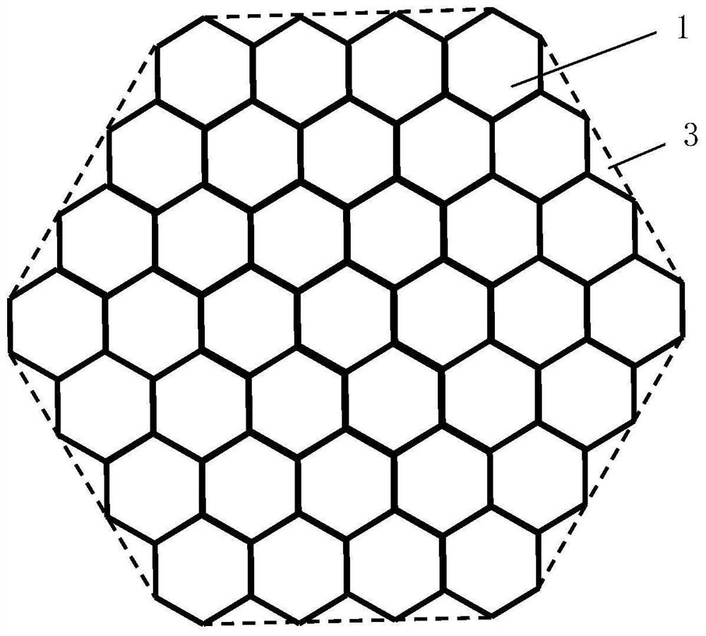
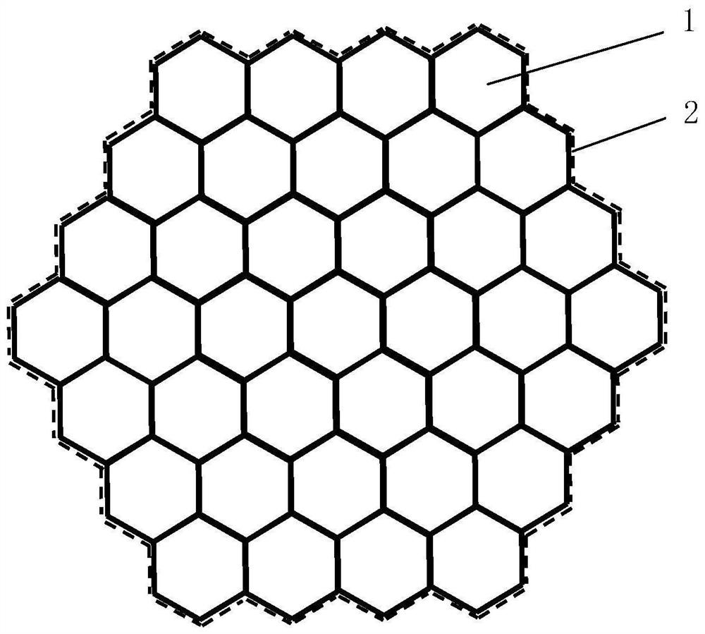
[0096] by image 3 37 optical fiber filaments are arranged in the arrangement shown, the length of the optical fiber filaments is 100 mm, and the circumference of the cross section is 24.2 mm. The silica gel heat-shrinkable film...

Embodiment 2

[0099] The preparation method of embodiment 2 is the same as that of embodiment 1, except that the proportioning of raw materials is different, and the raw materials are weighed according to the formula amount of embodiment 2 in table 1.

[0100] After testing, the properties of the cage-type oligomeric silsesquioxane-modified silica gel heat-shrinkable film obtained in Example 2 are listed in Table 1.

[0101] according to image 3 Arranged in the manner shown, using the cage-type oligomeric silsesquioxane-modified silica gel heat-shrinkable film obtained in Example 2 to bind 37 optical fiber filaments, and to test the inclination angle to test the silica gel heat-shrinkable film Stability of the bundled optical fiber wire arrangement structure: when the inclination angle is 60°, the number of optical fiber wires sliding out from the optical fiber base plate is 7.


PUM

PropertyMeasurementUnit
thicknessaaaaaaaaaa
lengthaaaaaaaaaa
lengthaaaaaaaaaa

Abstract

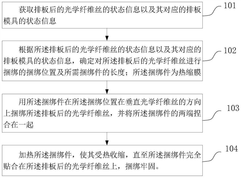
The invention relates to a method and a device for binding arranged optical fiber filaments. The method comprises the steps that: state information of the arranged optical fiber filaments and state information of a corresponding arranging mold are acquired; according to the state information of the arranged optical fiber filaments and the state information of the corresponding arranging mold, the binding position for binding the arranged optical fiber filaments and the length of a required binding piece are determined; the binding piece is a thermal shrinkage film; the binding piece is used for binding the arranged optical fiber filaments at the binding position in the direction perpendicular to the optical fiber filaments, and the two ends of the binding piece are kneaded together; and the binding piece is heated to enable the binding piece to be heated and shrunk until the binding piece is completely attached to the arranged optical fiber filaments, and firmly binding the optical fiber filaments. According to the method, the thermal shrinkage film is adopted for binding, and the contact area between the binding piece and the optical fiber filaments is increased, so that the stability of the optical fiber filament arrangement structure is ensured.

Description

technical field [0001] The invention relates to the field of manufacturing optical fiber panels, in particular to a method and a device for bundling optical fiber filaments after arranging the panels. Background technique [0002] Optical fiber panel (hereinafter referred to as optical fiber panel) is an optical fiber component formed by thousands of closely arranged optical fibers after arranging, hot-melting, annealing, rough machining and finishing. It has optical properties High light transmission efficiency, small inter-stage coupling loss, clear and true image transmission, zero thickness, etc. Optical fiber panels are widely used in various cathode ray tubes, camera tubes, CCD couplings and other instruments and equipment that need to transmit images. Among them, the large-area fiber optic panel is a key component used to make a large field of view low-light imager. Its application fields are very wide: the product can be used in medical field (such as X-ray machine...

Claims


Application Information

Patent Timeline
Patent Type & Authority Applications(China)
IPC IPC(8): G02B6/08
CPCG02B6/08Y02P40/57
Inventor 赵越贾金升张磊张弦汤晓峰石钰许慧超于浩洋张敬樊志恒宋普光洪常华王爱新
Owner CHINA BUILDING MATERIALS ACAD
Learn More