
Salty aerosol generator for testing filtering efficiency of filter material

An aerosol generator and filtration efficiency technology, which is applied in aerosol preparation, instruments, analysis materials, etc., can solve the problems of reducing the amount of liquid medicine, reducing the contact area, and reducing the depth of the liquid medicine, so as to ensure the small size and improve the forming efficiency. and quality, ensuring the effect of output efficiency and quality

Pending Publication Date: 2021-12-21
安徽省产品质量监督检验研究院
View PDF0 Cites 0 Cited by
  • Summary
  • Abstract
  • Description
  • Claims
  • Application Information

AI Technical Summary

Problems solved by technology

[0004] In the existing saline aerosol generator for material filtration efficiency test, since the volume of the liquid storage tank is a certain value, with the consumption of the liquid medicine in the liquid storage tank, the volume of compressed air in the liquid storage tank becomes larger and larger, resulting in The pressure of the high-speed airflow sprayed from the nozzle is reduced, which reduces the output efficiency and quality of the mist particles, and with the consumption of the liquid medicine in the storage tank, the depth of the liquid medicine gradually decreases, and the central part of the high-speed airflow is in contact with the liquid medicine. The reduction of the contact area reduces the amount of liquid medicine carried by the high-speed airflow, which eventually leads to a reduction of the mist particles formed through the nozzle, which cannot meet the requirements of the filter efficiency test.

Method used


Image

  • Salty aerosol generator for testing filtering efficiency of filter material
  • Salty aerosol generator for testing filtering efficiency of filter material
  • Salty aerosol generator for testing filtering efficiency of filter material

Examples


Embodiment Construction

[0028] In order to make the technical means, creative features, goals and effects achieved by the present invention easy to understand, the present invention will be further described below in conjunction with specific embodiments.

[0029] In the description of the present invention, it should be noted that the terms "upper", "lower", "inner", "outer", "front end", "rear end", "both ends", "one end", "another end" The orientation or positional relationship indicated by etc. is based on the orientation or positional relationship shown in the drawings, and is only for the convenience of describing the present invention and simplifying the description, rather than indicating or implying that the referred device or element must have a specific orientation, use a specific Azimuth configuration and operation, therefore, should not be construed as limiting the invention. In addition, the terms "first" and "second" are used for descriptive purposes only, and should not be understood ...


PUM


Abstract

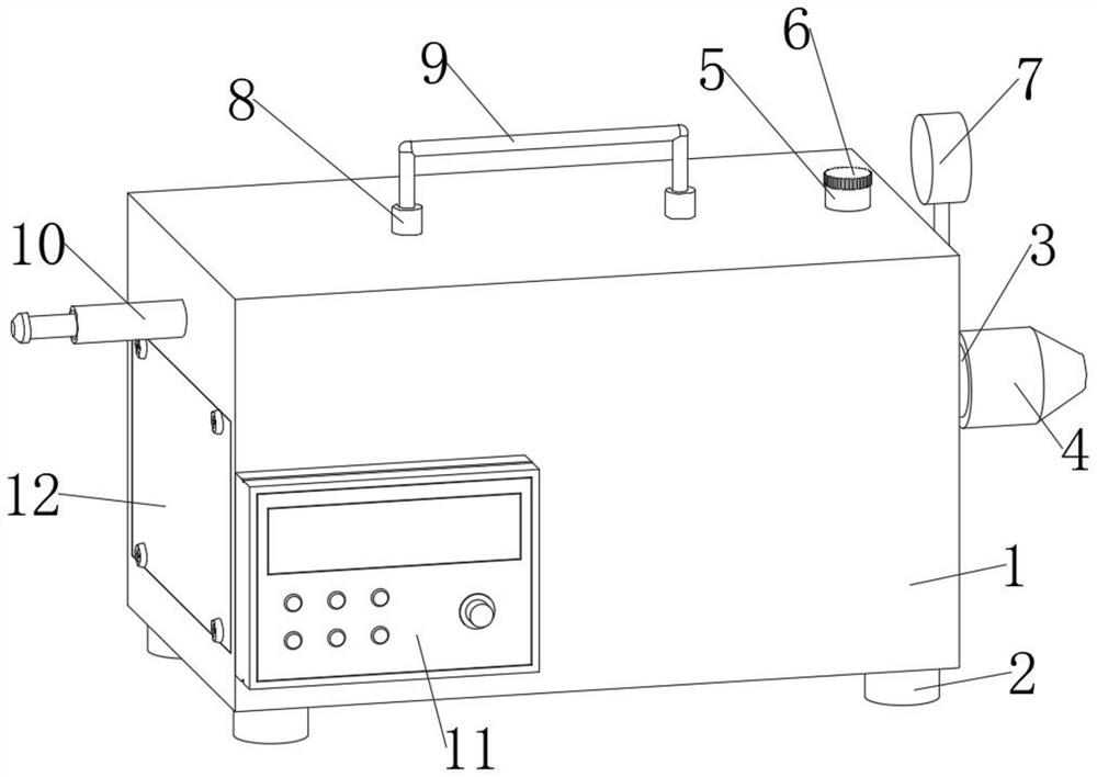
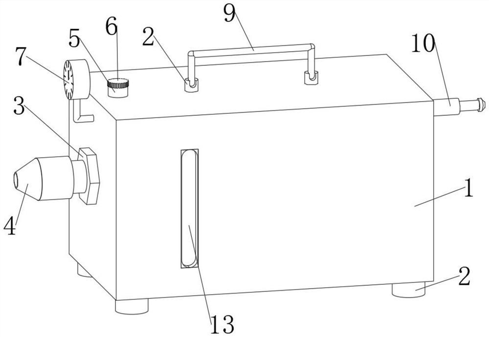
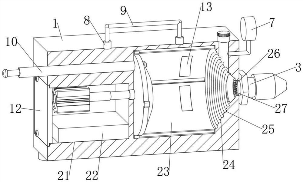
The invention discloses a salty aerosol generator for testing the filtering efficiency of a filter material. The generator comprises a shell, foot pads are fixedly mounted at four corners of the lower end of the shell, a connecting pipe is fixedly mounted in the middle of the right end of the shell, a nozzle is arranged at the right end of the connecting pipe, and a liquid injection opening is fixedly mounted at the right part of the upper end of the shell. The upper end of the liquid injection opening is in threaded connection with a sealing cover, a pressure detection meter is fixedly installed on the upper portion of the right end of the shell, the input end of the pressure detection meter extends into the shell, and two left-right symmetrical installation bases are fixedly installed in the middle of the upper end of the shell. According to the salty aerosol generator for testing the filtering efficiency of the filter material, aerosol is formed by arranging a liquid storage tank, a generating mechanism, the connecting pipe and the nozzle,the forming efficiency and quality of the aerosol are improved, the pre-acceleration function of high-speed airflow is achieved by arranging a funnel-shaped groove and the spiral air channel together in a matched mode, and the effect of improving the filtering efficiency of the filter material is achieved. And by arranging a liquid return plate and through holes, the forming efficiency of an aerosol-state liquid medicine is further improved.

Description

technical field [0001] The invention relates to the technical field of aerosol generators, in particular to a saline aerosol generator for filter efficiency testing. Background technique [0002] An aerosol generator is a suspension system of liquid or solid particles in the air. They can serve as condensation nuclei of water droplets and ice crystals (see atmospheric condensation nuclei, atmospheric ice nuclei), absorbers and scatterers of solar radiation, and participate in various chemical cycles, and are an important part of the atmosphere. Fog, smoke, haze, mist (haze), fine dust and smog are all atmospheric aerosols caused by natural or man-made reasons. [0003] The working principle of the saline aerosol generator: compressed air or oxygen (driving force) passes through the fine-mouth nozzle with high-speed airflow, and according to the Venturi effect, a negative pressure is generated around the nozzle to carry the liquid storage tank into the high-speed airflow and...

Claims


Application Information

Patent Timeline
IPC IPC(8): B01J13/00G01N15/08
CPCB01J13/0095G01N15/0806G01N2015/084
Inventor 陈静丁振华成清沈妍王红汪华陈蕾纪扬扬
Owner 安徽省产品质量监督检验研究院
Learn More