Supercharge Your Innovation With Domain-Expert AI Agents!

Clean and efficient garbage incineration power generation system

A technology of waste incineration and power generation system, applied in incinerators, combustion methods, combustion types, etc., can solve the problems of affecting power generation efficiency, reducing combustion efficiency, low combustion efficiency, etc., to improve cleanliness, improve combustion efficiency, and facilitate combustion. Effect

Pending Publication Date: 2021-12-24
兰溪旺能环保能源有限公司
View PDF0 Cites 0 Cited by
  • Summary
  • Abstract
  • Description
  • Claims
  • Application Information

AI Technical Summary

Problems solved by technology

However, because the garbage contains more moisture, although most of the filtrate will be filtered out after screening, there will still be a certain amount of moisture in the garbage. When the garbage containing moisture is directly sent into the grate furnace for burning , will lead to a reduction in combustion efficiency, and the moisture in the garbage needs to be dried before it can be burned, which in turn will affect the overall power generation efficiency
Therefore, the existing technology has the problem of low combustion efficiency

Method used


Image

  • Clean and efficient garbage incineration power generation system
  • Clean and efficient garbage incineration power generation system
  • Clean and efficient garbage incineration power generation system

Examples


Embodiment Construction

[0017] The present invention will be further described below in conjunction with the accompanying drawings and embodiments, but not as a basis for limiting the present invention.

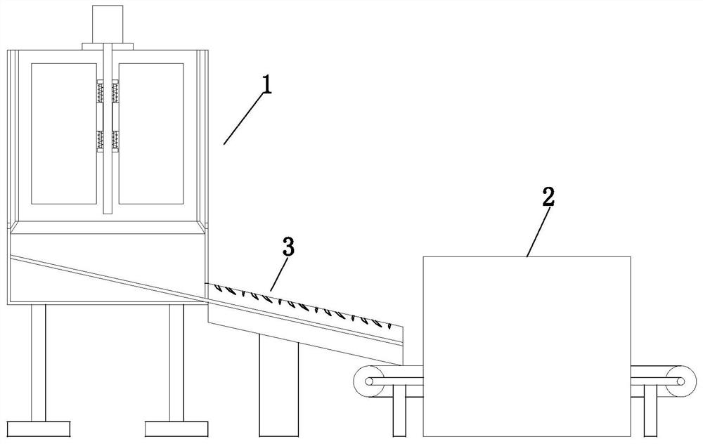
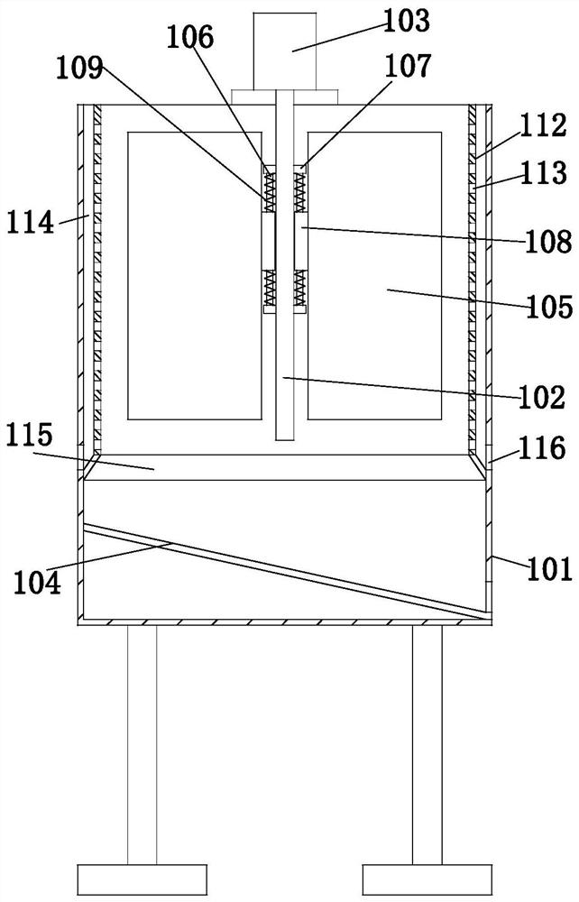
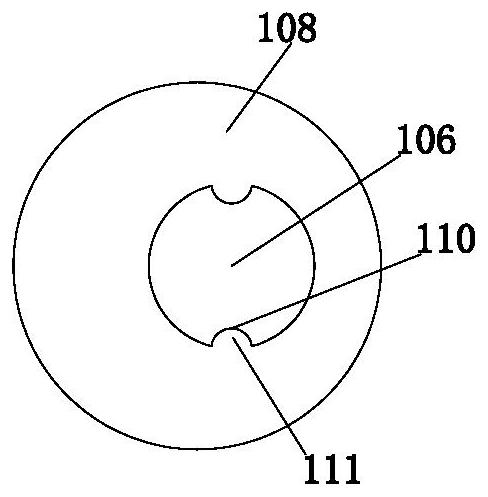
[0018] Example. A clean and efficient waste incineration power generation system consists of Figure 1 to Figure 5 As shown, it includes a garbage drying device, a grate furnace, a steam drum, a steam turbine and a generator connected in sequence; Between the dehydration box 1 and the garbage drying box 2, there is an obliquely distributed garbage conveying preheating channel 3; The upper end of the rotating rod 102 is provided with a drive motor 103, the dehydration rotating rod 102 is provided with a rotating assembly, and the bottom of the dehydration outer cylinder 101 is provided with an obliquely distributed water filter net 104, and the water filter net 104 cooperates with the garbage conveying preheating channel 3 The rotating assembly includes a plurality of circular vertical plates 105 d...


PUM


Abstract

The invention discloses a clean and efficient garbage incineration power generation system. The clean and efficient garbage incineration power generation system comprises a garbage drying device, a grate furnace, a steam pocket, a steam turbine and a power generator which are sequentially connected; the garbage drying device comprises a garbage dewatering box, a garbage drying box is arranged below the garbage dewatering box, and a garbage conveying and preheating channel which is obliquely distributed is arranged between the garbage dewatering box and the garbage drying box; the garbage dewatering box comprises a dewatering outer barrel, a dewatering rotating rod is arranged in the middle of the interior of the dewatering outer barrel, a driving motor is arranged at the upper end of the dewatering rotating rod, a rotating assembly is arranged on the dewatering rotating rod, a water filter screen which is obliquely distributed is arranged at the bottom of the dewatering outer barrel, and the water filter screen is matched with the garbage conveying and preheating channel; and the rotating assembly comprises a plurality of vertical plates annularly distributed on the dewatering rotating rod, and a vertical moving mechanism is arranged between the vertical plates and the dewatering rotating rod. The power generation system has the characteristic that the combustion efficiency can be effectively improved.

Description

technical field [0001] The invention relates to a waste incineration power generation system, in particular to a clean and efficient waste incineration power generation system. Background technique [0002] The thermal power plant uses the boiler to burn garbage, coal and other substances to generate steam, and then drives the generator set to move to complete the power generation process, mainly including the grate furnace, steam drum, steam turbine and generator set. The garbage is burned in the combustion chamber of the grate furnace. After the heat exchange of the heat exchanger in the combustion chamber of the grate furnace, steam is generated and enters the steam drum, and then the steam drives the steam turbine to operate, and then drives the generator set to generate electricity. However, because the garbage contains more moisture, although most of the filtrate will be filtered out after screening, there will still be a certain amount of moisture in the garbage. When...

Claims


Application Information

Patent Timeline
Patent Type & Authority Applications(China)
IPC IPC(8): F23G5/04F23G5/44F23G5/46F22B33/18F01D15/10
CPCF23G5/04F23G5/44F23G5/444F23G5/46F22B33/18F01D15/10F23G2206/203F23G2201/10F23G2201/20Y02E20/12
Inventor 何建威
Owner 兰溪旺能环保能源有限公司
Features
  • R&D
  • Intellectual Property
  • Life Sciences
  • Materials
  • Tech Scout
  • Unparalleled Data Quality
  • Higher Quality Content
  • 60% Fewer Hallucinations
Learn More