Yaw optimization control method based on airborne radar on-line yaw system

An airborne radar, optimized control technology, applied in the control of wind turbines, engine control, engine control parameters, etc., can solve the problems of affecting yaw control, large yaw error, and reduced accuracy, and achieve the purpose of extending operating life. Effect

Pending Publication Date: 2021-12-28
HUANENG CLEAN ENERGY RES INST +3
View PDF9 Cites 0 Cited by
  • Summary
  • Abstract
  • Description
  • Claims
  • Application Information

AI Technical Summary

Problems solved by technology

The yaw system is an important part of the wind turbine control system, and the yaw error is also an important performance index of the wind turbine, that is, the difference between the measured wind direction and the yaw angle of the unit has a great impact on the power generation. If it is too large, it will reduce the utilization rate of wind energy, reduce the power generation, increase the fatigue load of the unit and reduce the service life of the wind turbine
[0003] At present, wind turbines obtain wind energy to the greatest extent by controlling the yaw error. The measurement of wind direction in the control system is mainly done through the wind vane. Since the wind turbine operates in a complex external environment, such as low temperature and icing, the wind vane is often affected by the external environment. Due to the influence of complex environmental conditions, the wind direction cannot be accurately measured, and the decrease in accuracy leads to the inability of the wind turbine to obtain accurate yaw errors, which in turn affects the yaw control

Method used


Image

  • Yaw optimization control method based on airborne radar on-line yaw system
  • Yaw optimization control method based on airborne radar on-line yaw system
  • Yaw optimization control method based on airborne radar on-line yaw system

Examples


Embodiment

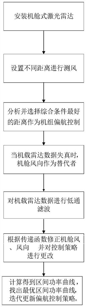
[0060] The invention provides a yaw optimization control method based on an airborne radar online yaw system, which includes the following steps: eliminating the influence of terrain on wind direction, determining the wind speed and direction of an airborne laser radar at the second level, data screening, and determining the airborne laser radar Radar measured distance, crew yaw control.

[0061] Eliminate the influence of terrain on wind direction;

[0062] 1) The airborne laser radar uses the principle of Doppler frequency shift to measure wind resource and wind condition parameters. In the atmosphere, the direction and speed of aerosol and wind movement are consistent, and the fiber laser emits a single beam with good coherence. When the beam encounters the moving aerosol particles in the atmosphere, it will produce radiation scattering of light, and the component scattered in the direction of the beam will produce the Doppler effect, and the frequency shift is detected on ...


PUM


Abstract

The invention discloses a yaw optimization control method based on an airborne radar on-line yaw system. The method comprises the following steps that an airborne laser radar is adopted to measure wind regime parameters of a wind resource; a yaw error value is calculated according to the wind regime parameters measured by the airborne laser radar, and a unit yaw control PLC sends out a yaw instruction according to the yaw error value to conduct yaw optimization control. The airborne laser radar is arranged, the wind regime parameters in front of a wind wheel are measured according to the laser generated by the laser radar, the upcoming actual wind regime of a wind turbine can be known in advance, whether yawing is conducted or not is judged in advance, a wind turbine generator set conducts corresponding yawing strategies or other control strategies in advance according to the wind regime parameters, and finally, the effects of prolonging the unit operation life, improving the unit safe operation coefficient and improving the unit generating capacity are achieved.

Description

technical field [0001] The invention belongs to the field of wind turbine control, in particular to a yaw optimization control method based on an airborne radar online yaw system. Background technique [0002] With the increasing number of wind turbines connected to the grid, performance testing of wind turbines becomes more and more important. The yaw system is an important part of the wind turbine control system, and the yaw error is also an important performance index of the wind turbine, that is, the difference between the measured wind direction and the yaw angle of the unit has a great impact on the power generation. If it is too large, it will reduce the utilization rate of wind energy, reduce the power generation, increase the fatigue load of the unit and reduce the service life of the wind turbine. [0003] At present, wind turbines obtain wind energy to the greatest extent by controlling the yaw error. The measurement of wind direction in the control system is mai...

Claims


Application Information

Patent Timeline
IPC IPC(8): F03D7/00F03D17/00
CPCF03D7/00F03D17/00F05B2270/329F05B2270/404F05B2270/504F05B2270/32F05B2270/321Y02E10/72
Inventor 卢坤鹏刘鑫闫姝张波尹铁男许世森樊启祥李来龙曹庆伟陈晓路杭兆峰刘溟江管春雨
Owner HUANENG CLEAN ENERGY RES INST
Why Eureka
Try Eureka