High-pressure filter press based on oil cylinder displacement control

A filter press, high pressure technology, applied in the field of high pressure filter press, can solve the problems of water and oil contact pollution, high failure rate, fracturing and other problems

Active Publication Date: 2022-01-04
山东菲特环保设备有限公司
View PDF16 Cites 0 Cited by
  • Summary
  • Abstract
  • Description
  • Claims
  • Application Information

AI Technical Summary

Problems solved by technology

[0003] To this end, there are two solutions in the prior art, one is to set a pressure conversion cylinder between the main cylinder and the high-pressure water pipe that provides pressure inside the chamber, and the pressure conversion cylinder can transfer the pressure of the high-pressure water pipe to the main cylinder , the main cylinder is connected to the outside of the filter plate to maintain the pressure. This solution needs to set up a pressure conversion cylinder with complex mechanical structure and high cost, and the pressure conversion cylinder may be polluted by water and oil contact
The second is to detect the feed pressure or water inlet pressure, and calculate the target oil pressure of the master cylinder based on the feed pressure or water inlet pressure according to a predetermined relationship, and then control the oil pressure of the master cylinder to reach the target oil pressure (for example, CN108525359B ), this method involves the detection and control of the oil pressure of the master cylinder, and is not suitable for occasions involving multiple master cylinders, because the simultaneous detection and cooperative control of the oil pressure of multiple master cylinders is usually very difficult, and this scheme cannot be accurate To control the dynamically changing lateral spacing between filter plates, the control accuracy is low, and it is easy to leak or filter plate fracturing, and the failure rate is very high in actual production

Method used


Image

  • High-pressure filter press based on oil cylinder displacement control
  • High-pressure filter press based on oil cylinder displacement control
  • High-pressure filter press based on oil cylinder displacement control

Examples


no. 1 example

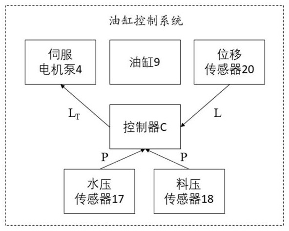
[0053] In a first embodiment, the controller C is configured to perform the following functions:

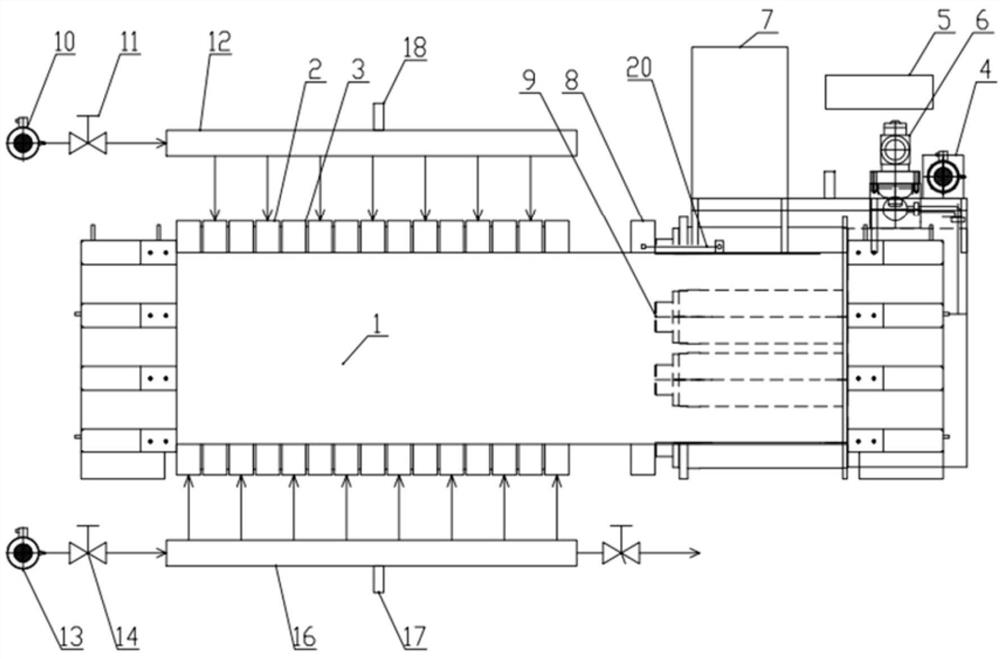
[0054] 1) Receive the current pressure value P from the water pressure sensor 17 or the material pressure sensor 18, which is the feed pressure in the first stage of dehydration, and the inlet water pressure in the second stage of dehydration;

[0055] 2) Based on the current pressure value P, determine the target displacement value L according to the corresponding relationship stored in the controller C T ;

[0056] 3) Based on the target displacement value L T , send a control signal to control the servo motor pump 4 to work, so that the displacement L of the oil cylinder 9 increases;

[0057] 4) When the current displacement L of the cylinder 9 reaches the target displacement value L T Afterwards, the work of controlling the servo motor pump 4 is stopped.

[0058] In the present invention, the pressure value P and the target displacement value L are determined through pre-...

no. 2 example

[0063] Based on the above relationship (1), the following relationship can be further obtained:

[0064] ΔL T =kΔP (2)

[0065] Among them, ΔP is the difference between the pressure values ​​P of the pressure fluid at two adjacent measurement moments, that is, the pressure change value; ΔL T is the target displacement value L of the oil cylinder corresponding to two adjacent measurement moments T The difference is the displacement change value.

[0066] Based on the above relationship (2), in the second embodiment, the controller C is configured to perform the following functions:

[0067] 1) Receive the current pressure value P from the water pressure sensor 17 or material pressure sensor 18;

[0068] 2) Based on the current pressure value P, determine its pressure change value ΔP relative to the pressure value at the previous measurement moment;

[0069] 3) Based on the pressure change value ΔP, and ΔP and ΔL T The corresponding relationship between, such as the a...

no. 3 example

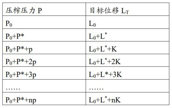
[0072] Based on the above relationship (2), if ΔP is taken as a fixed value p, for example, it can be 0.5 Mpa, since k and p are both fixed values, ΔL T is also a fixed value, denoted as K, and the following relationship can be further obtained at this time:

[0073] K = k·p (3)

[0074] Based on the above relationship (3), in the third embodiment, the controller C is configured to perform the following functions:

[0075] 1) Receive the current pressure value P from the water pressure sensor 17 or material pressure sensor 18;

[0076] 2) Monitor the change of the pressure value P. Whenever the pressure value P increases by a constant pressure increment p, a control signal is sent to control the operation of the servo motor pump 4, so that the displacement of the oil cylinder 9 increases by a corresponding constant displacement increment K .


PUM


Abstract

The invention provides a high-pressure filter press based on oil cylinder displacement control. A controller of the high-pressure filter press is configured to monitor the pressure value of a pressure fluid entering a closed chamber formed by a filter plate, and when the pressure value is increased by an initial pressure increment P* from an initial pressure P0, the controller sends out a control signal to control an oil cylinder to move by an initial displacement increment L*; and the pressure value continues to be monitored, and when the pressure value is increased by a constant pressure increment p, the controller sends out a control signal to control the oil cylinder to move by a constant displacement increment K. According to the above scheme, the control for maintaining the pressure is simple and accurate, cost is reduced, a failure rate is greatly reduced, and the high-pressure filter press can work under higher pressure, so filter pressing effect is improved.

Description

technical field [0001] The invention relates to the technical field of filter press equipment, in particular to a high-pressure filter press, which provides holding pressure based on the control of oil cylinder displacement. Background technique [0002] High-pressure filter presses are widely used in coal mines, sand washing, printing and dyeing, papermaking, environmental protection and other industries for the treatment of sewage or sludge. The basic principle of the high-pressure filter press is to apply pressure to the mud contained in the chamber formed by two filter plates, so that the water in it can be discharged. The higher the pressure, the more water is expelled. However, the higher the pressure, the two filter plates may separate and leak. To prevent leakage, a holding pressure needs to be applied on the outside of the filter plate. The pressure in the chamber is dynamically changing. If the holding pressure is too small, leakage will occur, and if the holdi...

Claims


Application Information

Patent Timeline
IPC IPC(8): B01D25/00B01D25/12B01D25/21F15B21/02F15B3/00
CPCB01D25/007B01D25/12B01D25/21F15B21/02F15B3/00F15B2211/6306F15B2211/6336F15B2211/20515
Inventor 姚蔚然
Owner 山东菲特环保设备有限公司
Why Eureka
Try Eureka