Fabricated wall for hospital

A prefabricated, hospital technology, applied in the direction of wall, thermal insulation, fire prevention, etc., can solve the problems of easy breeding of bacteria on the surface of the wall, insufficient functions of embedded equipment, affecting the sound insulation effect of the wall, etc., to achieve convenient and fast installation, good thermal insulation, The effect of shortening construction time

Active Publication Date: 2022-01-04
SHENZHEN UNIV +1
View PDF7 Cites 0 Cited by
  • Summary
  • Abstract
  • Description
  • Claims
  • Application Information

AI Technical Summary

Problems solved by technology

[0003] At present, the prefabricated walls used in hospitals are known to have poor sound insulation effect, poor fire resistance, easy breeding of bacteria on the surface of the wall, and insufficient functions of embedded equipment. Defects, this type of prefabricated wall used in hospitals has not adapted to the growing requirements for the development of multifunctional prefabricated walls used in hospitals; and the current material of the sound insulation layer is sound insulation cotton, which is usually filled into the wall The inner cavity of the body is filled to achieve a sound insulation effect, but this method requires a lot of manpower and material resources, and in the filling process, the sound insulation material is a light-weight floc. Through the filling method, it is possible It causes uneven dispersion in the cavity of the wall, which affects the sound insulation effect of the whole wall

Method used


Image

  • Fabricated wall for hospital
  • Fabricated wall for hospital
  • Fabricated wall for hospital

Examples


Embodiment 2

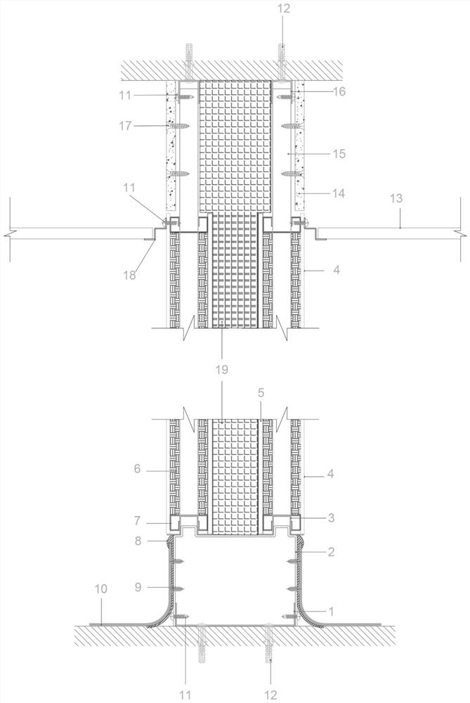
[0047] The present invention improves the sound insulation layer 19 to solve the problem that the current material of the sound insulation layer 19 is sound insulation cotton, which is usually filled into the inner cavity of the wall by filling, so as to achieve a sound insulation effect, but this method requires cost Large manpower and material resources, and in the filling process, the sound insulation material is a light-weight floc, which may cause uneven dispersion in the cavity of the wall through the filling method, affecting the sound insulation effect of the overall wall;

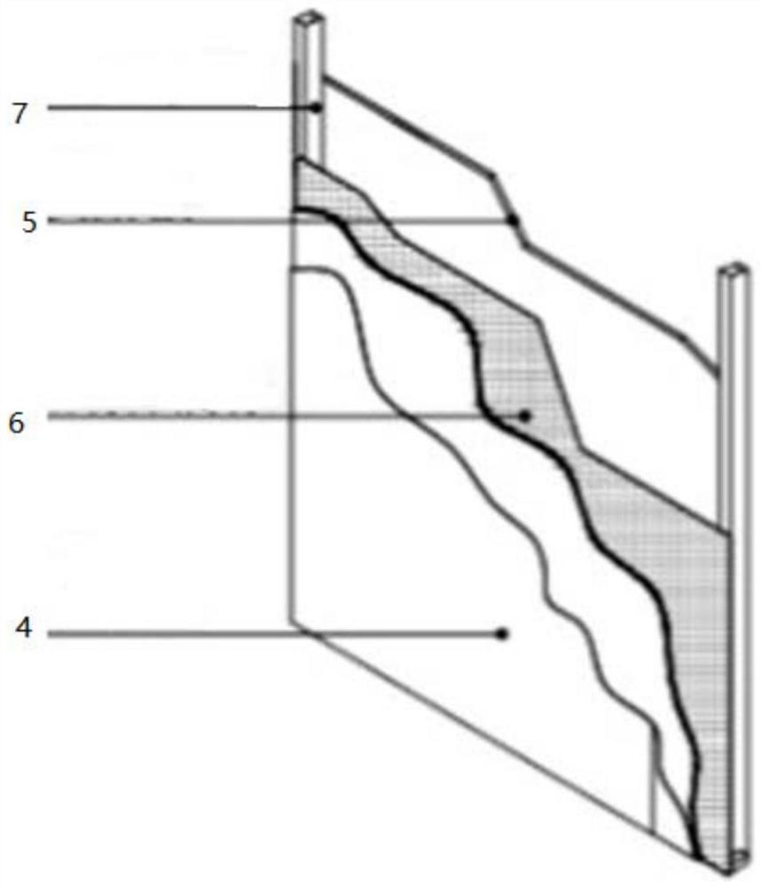
[0048] see Figure 5 and Figure 6 As shown, the specific improvement of the sound insulation layer 19 is: the sound insulation material is respectively loaded into the upper filling plate 26 and the lower filling plate 27, so that when the wall is installed, it can be installed in the wall as a whole, so that It can effectively solve the inconvenience of installation and the problem that the soun...

Embodiment 3

[0053] see Figure 7 As shown, both sides of the adjusting plate 30 are slidingly connected with the inner wall of the lower filling plate 27, wherein one end of the adjusting plate 30 is connected with the sliding plate 32, and the sliding plate 32 extends into the side wall cavity of the lower filling plate 27, and is connected with the lower filling plate. 27 is slidingly connected, and a screw rod 33 is vertically arranged in the inner cavity of the side wall of the lower filling plate 27, and the screw rod 33 runs through a plurality of slide plates 32 in turn, and the top end of the screw rod 33 extends to the top inner cavity of the lower filling plate 27, And be connected with connector 29;

[0054] When in use, the drive motor of the peripheral device is connected to the connector 29, and then the screw rod 33 is driven to rotate forward and reverse, so that the slide plate 32 moves up and down along the lower filling plate 27, and drives the adjustment plate 30 to mo...

Embodiment 4

[0057] see Figure 8-11 As shown, the upper filling plate 26 is connected with the lower filling plate 27 through the connector 29, the bottom sides of the upper filling plate 26 are respectively provided with plugs 35, the bottom of the plug 35 is provided with a mounting groove, and the two sides of the mounting groove are provided with a limiting plate 41, the limit plate 41 is slidably connected in the installation groove through the limit rod 42, the spring 43 is connected between the two sets of limit plates 41, the side of the limit plate 41 away from the spring 43 is provided with a pin block 36, and the connector 29 A mounting hole 39 adapted to the plug 35 is provided on the top, and the pin block 36 is a hemispherical structure;

[0058] When installing the upper filler plate 26 and the lower filler plate 27, the plug 35 at the bottom of the upper filler plate 26 is correspondingly inserted into the mounting hole 39 in the connector 29, and when the plug 35 reaches ...


PUM


Abstract

The invention discloses a fabricated wall for a hospital. The fabricated wall comprises keels, wallboard modules and sound insulation layers; the keels are installed above a ceiling, the wallboard modules are installed below the ceiling, and the sound insulation layers are arranged between the two sets of vertical keels above the keels and between calcium silicate bottom plates in the wallboard modules; each sound insulation layer comprises an upper filling plate and a lower filling plate which are filled with sound insulation materials, the upper filling plate is correspondingly positioned above the ceiling, and the lower filling plate is correspondingly positioned below the ceiling; and adjusting plates are arranged in an inner cavity of the lower filling plate at equal intervals, a lining plate is arranged between every two sets of adjusting plates, and the inner cavity of the lower filling plate is divided into a plurality of small cavities filled with the sound insulation materials through the adjusting plates and the lining plates. The fabricated wall has the functions of sound insulation, heat insulation, bacteriostasis of the outer surface of the wall and capability of being embedded into specific equipment such as a medical equipment box, a wall lamp and a socket panel; and the filling type sound insulation layers are arranged, the sound insulation efficiency of the wall body is improved, the service life of the sound insulation materials is prolonged, and the fabricated wall is mainly used for building hospital houses.

Description

technical field [0001] The invention relates to the technical field of building walls, in particular to an assembled wall for hospital buildings. Background technique [0002] Chinese patent CN214034376U discloses a prefabricated wall panel for hospitals, which relates to the technical field of building materials, including a wall panel, an adhesive curing layer is connected to the inner surface of the wall panel, and a Transverse steel bars and / or longitudinal steel bars, the horizontal steel bars and / or longitudinal steel bars protrude from the wallboard, grooves are arranged on the inner side of the wallboard, and the bonding and curing layer is filled into the grooves Inside. The prefabricated wall panel used in hospitals not only has good thermal insulation effect, but also has good strength performance of the wall, large supporting load-bearing capacity, good safety, quick assembly, low operation requirements for workers, high work efficiency, and greatly reduced labo...

Claims


Application Information

Patent Timeline
Patent Type & Authority Applications(China)
IPC IPC(8): E04B2/74E04B2/76E04B2/82E04B1/88E04B1/94
CPCE04B2/7407E04B2/7409E04B2/76E04B2/82E04B1/88E04B1/941E04B2002/7461E04B2002/7488
Inventor 邢立华石媛符永贤余妙龄刘瑞平
Owner SHENZHEN UNIV
Why Eureka
Try Eureka