
Clock Synchronization Method for Switching Mode DC Converter

A DC converter, switching technology, applied in the direction of converting DC power input to DC power output, high-efficiency power electronic conversion, output power conversion device, etc. The filter capacitor occupies a large chip area, large chip area and power consumption, etc., to achieve the effect of saving power consumption and area, saving power consumption, and eliminating additional duty cycle errors.

Active Publication Date: 2022-06-03
SUZHOU POWERLINK MICROELECTRONICS
View PDF4 Cites 0 Cited by
  • Summary
  • Abstract
  • Description
  • Claims
  • Application Information

AI Technical Summary

Problems solved by technology

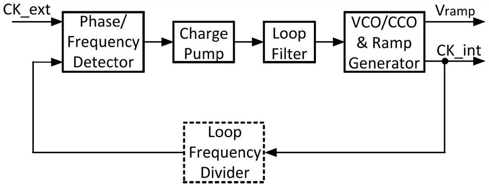
The disadvantage of this traditional method is that the phase-locked loop occupies a large chip area and power consumption
Especially when the bandwidth of the phase-locked loop is small, the capacitance in the loop filter occupies a large chip area, and even requires additional package pins and off-chip capacitance
Another important disadvantage of using a phase-locked loop is that, due to the limitation of the bandwidth of the phase-locked loop, if the frequency of the reference clock is modulated, the output oscillator clock may not keep up with the rapid changes of the reference clock

Method used


Image

  • Clock Synchronization Method for Switching Mode DC Converter
  • Clock Synchronization Method for Switching Mode DC Converter
  • Clock Synchronization Method for Switching Mode DC Converter

Examples


Embodiment Construction

[0040] The technical solutions in the embodiments of the present invention will be clearly and completely described below with reference to the accompanying drawings in the embodiments of the present invention. Based on the embodiments of the present invention, all other embodiments obtained by those of ordinary skill in the art without creative efforts shall fall within the protection scope of the present invention.

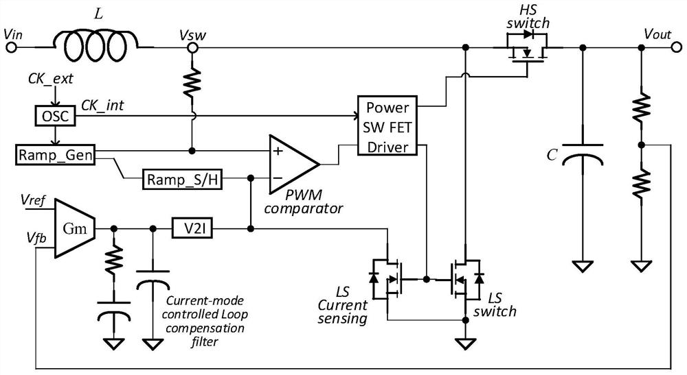
[0041] figure 1 Shown is a typical switching DC converter, a current-controlled mode DC boost converter (Boost). According to the magnitude of the load current, the DC converter works in two states: Pulse Width Modulation (PWM) or Pulse Frequency Modulation (PFM). If the input and output voltages of the Boost are respectively V in and V out , then the duty cycle of the gate drive voltage of the low-side switch in the PWM working state is:

[0042]

[0043] Therefore, according to the application when the minimum input voltage V in with the maximum output...


PUM


Abstract

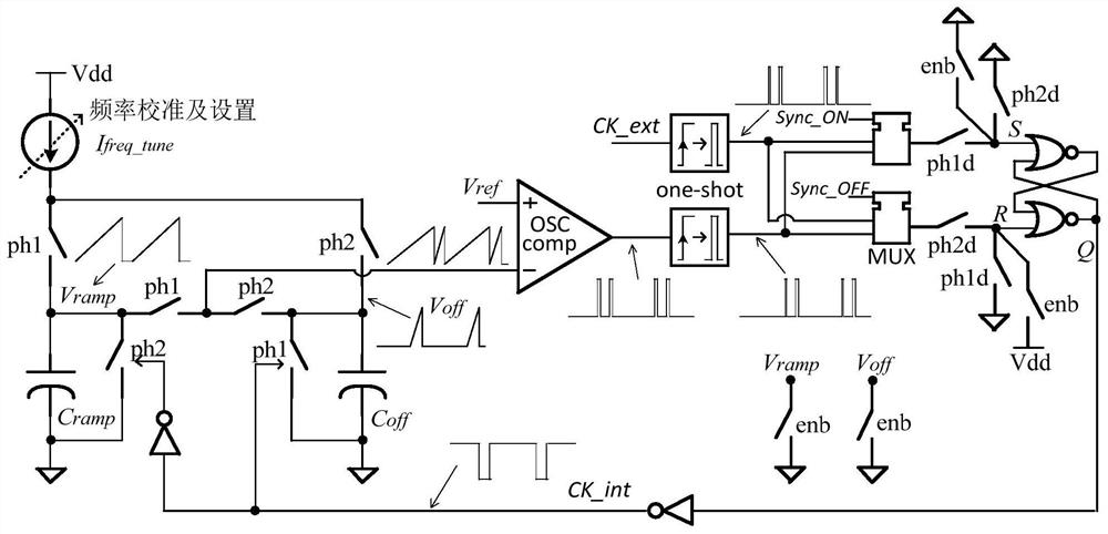
The invention discloses a clock synchronization method of a switching mode DC converter (switching-mode DC-DC converter), which belongs to the technical field of chip design. Off-chip input clock synchronization technology. The present invention maintains the duty cycle (DC: duty cycle) of the voltage ramp (voltage ramp) required by the on-chip clock and current control mode; and the relaxation oscillator shares a comparator, which not only saves the area and power consumption of the chip, The additional accuracy loss caused by the difference in the offset voltages of the two comparators is eliminated. Compared with the traditional method requiring a phase-locked loop, the present invention greatly saves chip area and power consumption, and uses a frequency-programmable oscillator to maintain the flexibility of a synchronizable clock frequency.

Description

technical field [0001] The invention belongs to a clock synchronization method of an on-chip switching DC converter in a pulse width modulation (PWM) working state, belongs to the technical field of chip design, and in particular relates to an on-chip switching clock and on-chip switching clock that saves chip area and power consumption. Synchronization method of external input clock. Background technique [0002] In some switching DC converter applications, for reasons such as reducing electromagnetic interference and control noise, it is necessary to synchronize the switching clock of the switching DC converter (Buck, Boost, Buck-Boost, etc.) with the off-chip input clock . The most direct and most commonly used clock synchronization method is to use a phase-locked loop circuit. The off-chip input clock is used as the reference clock of the phase-locked loop, and the output clock of the oscillator in the phase-locked loop is used as the switch control of the DC converter...

Claims


Application Information

Patent Timeline
Patent Type & Authority Patents(China)
IPC IPC(8): H03K5/156H03K7/08H02M3/156H02M3/158
CPCH03K5/156H03K7/08H02M3/156H02M3/1582Y02B70/10
Inventor 宋文星韩兴成万海军
Owner SUZHOU POWERLINK MICROELECTRONICS
Learn More