
Energy-saving control method for reactive voltage automatic control system of wind power plant and photovoltaic power station

A technology of automatic voltage control and photovoltaic power plants, applied in wind power generation, reactive power compensation, system integration technology, etc., can solve the problem that the reactive power adjustment capacity of generators cannot be fully utilized, affecting new energy stations, and the signs of reactive power equipment are reversed, etc. problems, to achieve the effect of optimizing economic operation, improving safety, stability and economy, and enhancing the ability of voltage mutation

Pending Publication Date: 2022-01-21
安智科为新能源集团有限公司
View PDF0 Cites 0 Cited by
  • Summary
  • Abstract
  • Description
  • Claims
  • Application Information

AI Technical Summary

Problems solved by technology

[0005] Part of the AVC system adopts the voltage control mode in the process of controlling the reactive power compensation device, that is, the AVC system will forward the bus voltage target value issued by the master station to the reactive power compensation device, and the reactive power compensation device will control it by itself, so as to realize the voltage control mode. In this case, affected by various factors such as the accuracy of the PT / CT hardware equipment connected to the on-site reactive power compensation device, software control logic, response time of the generator and reactive power compensation device, etc., reactive power equipment will also appear The sign is opposite, the reactive power adjustment ability of the generator cannot be fully utilized, etc., which seriously affect the safety, stability and economy of the operation of the new energy station

Method used


Image

  • Energy-saving control method for reactive voltage automatic control system of wind power plant and photovoltaic power station
  • Energy-saving control method for reactive voltage automatic control system of wind power plant and photovoltaic power station

Examples


Embodiment 1

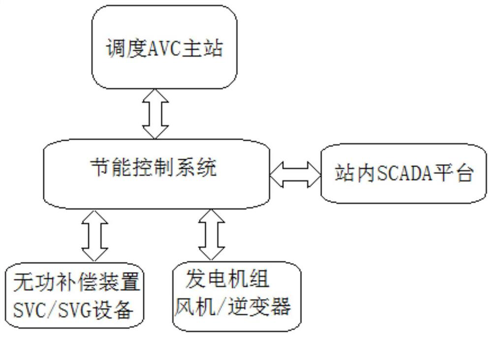
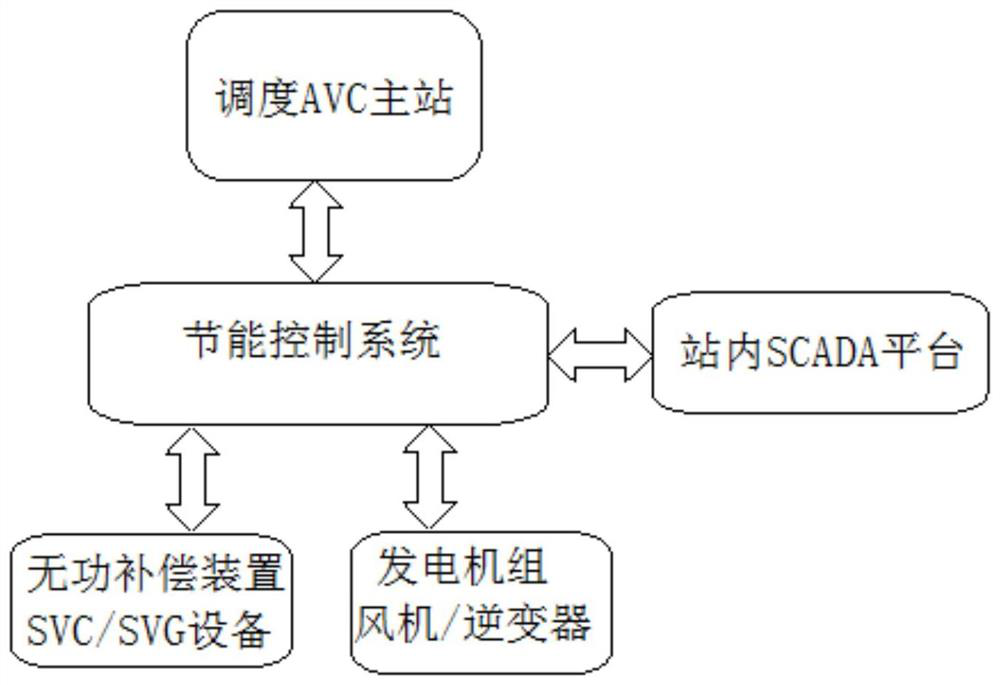
[0023] Such as figure 1 The energy-saving control method of the reactive power and voltage automatic control system of the wind farm and photovoltaic power station shown in the figure, on the basis of ensuring the safe and stable operation of the wind farm and photovoltaic power station, further improves the economy of the power plant operation by rationally optimizing the reactive power output in the distribution station ; Compatible with cluster control mode and stand-alone control mode, taking into account the safe and stable operation of buses with different voltage levels, avoiding voltage imbalance that may occur in the case of multiple 35kV buses, and avoiding the reactive power output of multiple reactive devices in the station symbol In the opposite situation, priority is given to adjusting the reactive power of the generator set, and try to reserve more adjustment margins for the reactive power compensation device, so that the ability of the new energy station to deal...


PUM


Abstract

The invention discloses an energy-saving control method for a reactive voltage automatic control system of a wind power plant and a photovoltaic power station. The method specifically comprises the following steps: firstly, carrying out data communication between a station and a dispatching AVC main station, then collecting the operation state and parameters, finally, processing the data in the station, and after the station receives a voltage target value issued by the dispatching AVC main station, through analysis and calculation, converting a voltage regulating variable into a reactive regulating variable, then calculating a reactive regulation target of each device in real time according to operation states and operation parameters of each unit and each device, and issuing the target value to each platform or device. According to the energy-saving control method for the reactive voltage automatic control system of the wind power plant and the photovoltaic power station, economical operation of the reactive voltage automatic control system is optimized, and meanwhile, the safe and stable operation of each device in the power plant is further ensured by performing more reasonable optimal distribution on each device with a reactive power output function in the station.

Description

technical field [0001] The invention specifically relates to an energy-saving control method for a reactive voltage automatic control system of a wind farm and a photovoltaic power station, and belongs to the technical field of reactive voltage automatic control systems. Background technique [0002] With the rapid development of economy and industrialization, traditional fossil energy is gradually exhausted, environmental damage is becoming more and more serious, and the demand for renewable energy is increasing. Wind power and photovoltaic power generation are increasingly attracting global attention; wind power and photovoltaic units are used in new energy. The proportion is constantly increasing, and their impact on the power system cannot be ignored; due to the randomness and intermittent characteristics of wind energy and solar energy, it is difficult to accurately predict the changing trend of new energy power generation output, resulting in difficulties and complicati...

Claims


Application Information

Patent Timeline
Patent Type & Authority Applications(China)
IPC IPC(8): H02J3/16H02J3/50H02J3/26H02J13/00
CPCH02J3/16H02J3/50H02J3/381H02J3/26H02J13/00001H02J2300/22H02J2300/28H02J2300/40Y02E10/76Y02E40/30Y02E40/50Y02E40/70Y04S10/50Y04S10/123
Inventor 董振阳闫功吴志健彭以光孔启翔
Owner 安智科为新能源集团有限公司
Learn More