Communication signal control method and system based on laser energy supply network
A communication signal and laser energy supply technology, which is applied in optical fiber transmission, remote measurement/remote control selection device, transportation and packaging, etc., can solve the problems of mutual interference of the same optical fiber channel, mutual interference of data transmission optical fiber channels, and affecting the stability of information performance, etc.
- Summary
- Abstract
- Description
- Claims
- Application Information
AI Technical Summary
Problems solved by technology
Method used
Image
Examples
Embodiment 1
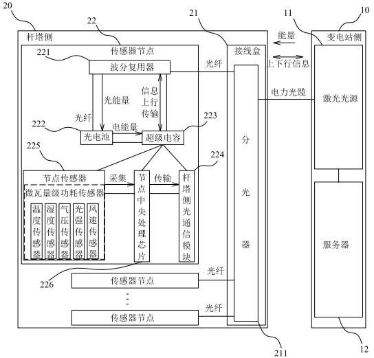
[0041] This embodiment provides a communication signal control method based on a laser energy supply network, which is applied to a communication signal control system based on a laser energy supply network. Such as figure 2 As shown, the communication signal control system based on the laser energy supply network includes a substation side 10 and a tower side 20 . Wherein, the substation side 10 is provided with a laser light source 11 and a server 12 , and the tower side 20 is provided with a beam splitter 211 optically connected to the laser light source 11 and a plurality of sensor nodes 22 . Specifically, the optical splitter 211 is arranged in the junction box 21 , and the laser energy signals and information communication signals transmitted from the substation side 10 are distributed to a plurality of the sensor nodes 22 as required through the optical splitter 211 .
[0042] Further, each sensor node 22 is equipped with a wavelength division multiplexer 221 , a phot...
Embodiment 2
[0058] This embodiment provides a communication signal control method based on a laser energy supply network, which is applied to a communication signal control system based on a laser energy supply network. Such as Figure 4 As shown, the communication signal control system based on the laser energy supply network includes a substation side 10 and a tower side 20 . Wherein, the substation side 10 is provided with a laser light source 11 and a server 12 , and the tower side 20 is provided with a beam splitter 211 optically connected to the laser light source 11 and a plurality of sensor nodes 22 . Specifically, the optical splitter 211 is arranged in the junction box 21 , and the laser energy signals and information communication signals transmitted from the substation side 10 are distributed to a plurality of the sensor nodes 22 as required through the optical splitter 211 .
[0059] Further, each sensor node 22 is equipped with a wavelength division multiplexer 221 , a phot...
Embodiment 3
[0073] This embodiment provides a communication signal control method based on a laser energy supply network, which is applied to a communication signal control system based on a laser energy supply network. Such as Figure 5 As shown, the communication signal control system based on the laser energy supply network includes a substation side 10 and a tower side 20 . Wherein, the substation side 10 is provided with a laser light source 11 and a server 12 , and the tower side 20 is provided with a beam splitter 211 optically connected to the laser light source 11 and a plurality of sensor nodes 22 . Specifically, the optical splitter 211 is arranged in the junction box 21 , and the laser energy signals and information communication signals transmitted from the substation side 10 are distributed to a plurality of the sensor nodes 22 as required through the optical splitter 211 .
[0074] Further, each sensor node 22 is equipped with a wavelength division multiplexer 221 , a phot...
PUM
 Abstract
Description
Claims
Application Information
 - R&D
- Intellectual Property
- Life Sciences
- Materials
- Tech Scout
- Unparalleled Data Quality
- Higher Quality Content
- 60% Fewer Hallucinations
Browse by: Latest US Patents, China's latest patents, Technical Efficacy Thesaurus, Application Domain, Technology Topic, Popular Technical Reports.
© 2025 PatSnap. All rights reserved.Legal|Privacy policy|Modern Slavery Act Transparency Statement|Sitemap|About US| Contact US: help@patsnap.com


