Diffusion oxidation annealing furnace thermostatic bath control circuit improvement process
A technology of control circuit and diffusion oxidation, applied in furnace control device, furnace, furnace cooling and other directions, can solve problems such as affecting the service life of thermostatic bath, disconnection of air switch, and overheating of devices, so as to improve the yield of production line and ensure The effect of normal operation and improved cooling effect
- Summary
- Abstract
- Description
- Claims
- Application Information
AI Technical Summary
Problems solved by technology
Method used
Image
Examples
Embodiment 1
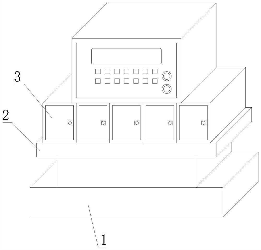
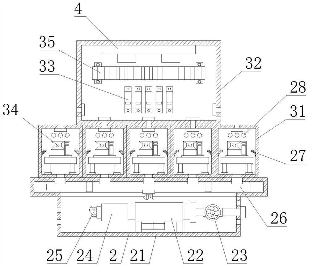
[0035] like Figure 1-7As shown, the present invention provides a process for improving the control circuit of the constant temperature tank of a diffusion oxidation annealing furnace, including a main engine base 1, a constant temperature tank heat dissipation mechanism 2 is arranged on the top of the main engine base 1, and a control The circuit improvement mechanism 3 and the top of the control circuit improvement mechanism 3 are provided with a fire prevention mechanism 4, and the constant temperature tank heat dissipation mechanism 2 includes a T-shaped support platform 21, which is fixedly installed on the top of the host base 1, and the T-shaped support platform 21 A dehumidification box 22 is fixedly installed at the bottom of the inner cavity, and a heat dissipation fan 23 is fixedly connected to the right side of the dehumidification box 22. The air inlet pipe of the heat dissipation fan 23 extends to the right side of the T-shaped support platform 21. The control cir...
Embodiment 2
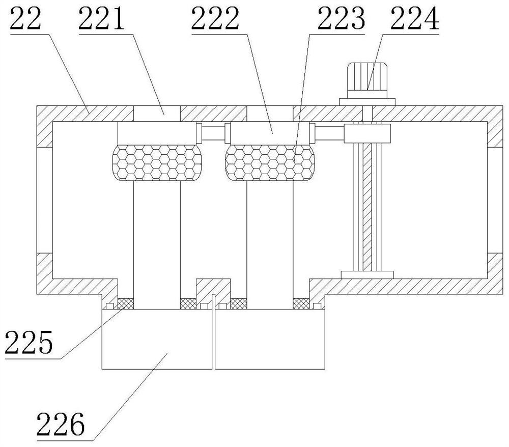
[0037] like Figure 1-7 As shown, on the basis of Embodiment 1, the present invention provides a technical solution: preferably, the left side of the dehumidification box body 22 is detachably connected with a detachable connecting pipe 24, and the left side of the dehumidifying connecting pipe 24 is threadedly connected with a connection Flexible hose 25, the inner cavity of the detachable connecting pipe 24 is filled with activated carbon, the top of the inner cavity of the T-shaped support platform 21 is fixedly installed with a shunt pipe 26, and the end of the connecting hose 25 away from the detachable connecting pipe 24 is connected to the bottom of the shunt pipe 26 Threaded connection, the back of the branch box 31 is provided with an air outlet 28, both sides of the inner cavity of the branch box 31 are fixed with guide plates 27, the top of the branch pipe 26 and the bottom of the branch box 31 are fixed by plastic air ducts Connection, the cooling square tube 221 i...
Embodiment 3
[0039] like Figure 1-7 As shown, on the basis of Example 1, the present invention provides a technical solution: preferably, the bottom of the inner cavity of the cooling square tube 221 is fixedly installed with a rock wool blocking square tube 2211, and the front and back of the rock wool blocking square tube 2211 Both of them are fixedly installed with a semiconductor refrigerating sheet 2212, the cold end of the semiconductor refrigerating sheet 2212 is set on the outer wall of the rock wool blocking square tube 2211, and the hot end of the semiconductor refrigerating sheet 2212 is set in the inner cavity of the rock wool blocking square tube 2211, the semiconductor cooling sheet 2212 The hot end of the sheet 2212 is fixedly equipped with cooling fins, the bottom of the inner cavity of the cooling square tube 221 is fixedly equipped with a hollow support tube 2214, the top of the hollow support tube 2214 is fixedly connected with a hot end heat dissipation pipe 2213, and t...
PUM
 Abstract
Description
Claims
Application Information
 - R&D
- Intellectual Property
- Life Sciences
- Materials
- Tech Scout
- Unparalleled Data Quality
- Higher Quality Content
- 60% Fewer Hallucinations
Browse by: Latest US Patents, China's latest patents, Technical Efficacy Thesaurus, Application Domain, Technology Topic, Popular Technical Reports.
© 2025 PatSnap. All rights reserved.Legal|Privacy policy|Modern Slavery Act Transparency Statement|Sitemap|About US| Contact US: help@patsnap.com


