Battery pole piece, preparation method thereof, and lithium-ion battery

A lithium-ion battery, pole piece technology, applied in electrode manufacturing, battery electrodes, electrode rolling/calendering, etc., can solve the problems of reducing battery energy density, increasing processes, reducing consistency, etc., to improve energy density, improve rolling Compression density, effect of changing the number of welds

Active Publication Date: 2022-05-10
TIANJIN LISHEN BATTERY +1
View PDF8 Cites 0 Cited by
  • Summary
  • Abstract
  • Description
  • Claims
  • Application Information

AI Technical Summary

Problems solved by technology

[0005] At present, in order to solve the internal resistance problem of welding tabs, many manufacturers adopt multi-tab structure, but it will reduce the energy density of the battery, and the battery of the same size will increase the weight of the battery cell, and the consistency of the battery cell will be reduced during the production process and good products. The rate is reduced, the process increases the process, and the production efficiency of the battery is reduced

Method used


Image

  • Battery pole piece, preparation method thereof, and lithium-ion battery
  • Battery pole piece, preparation method thereof, and lithium-ion battery
  • Battery pole piece, preparation method thereof, and lithium-ion battery

Examples


Embodiment 1

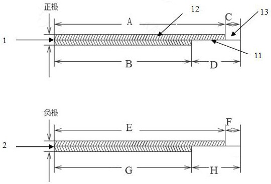
[0047] Example 1: figure 1 A lithium-ion battery pole piece is shown, including a positive electrode sheet 1 and a negative electrode sheet 2; the positive electrode sheet includes a positive electrode current collector 11, a positive electrode coating layer 12, and a positive aurora foil layer 13; the positive aurora foil layer includes The first positive aurora foil layer and the second positive aurora foil layer ( figure 1 The position of the first positive aurora foil layer and the second positive aurora foil layer coincide, the position of the second positive aurora foil layer remains unchanged, and the change of resistance is realized by changing the position of the first positive aurora foil layer); the positive electrode coating layer The end is the second positive aurora foil layer, and the first positive aurora foil layer divides the positive electrode coating layer into the first positive electrode coating layer and the second positive electrode coating layer; the p...

Embodiment 2

[0055] Embodiment 2: In another embodiment of the present application, similar to Embodiment 1, the only difference is that the position of the first positive aurora foil layer is different, such as Figure 4-5 It is shown that the position of the first positive aurora foil layer is at 1 / 10-9 / 10 of the positive plate, by Image 6 According to the simulation calculation, compared with the negative tab, the potential potential of the positive tab welding position is the lowest, and at the same time, Figure 7 As shown, the position of the tab (that is, the position of the first positive aurora foil layer), under the simulated rate discharge, under the state of 100% SOC 1C discharge for 10s, the internal resistance is the smallest at the 40% position, so Example 2 adopts 40% position for welding. The battery electrode group is made into a lithium-ion battery, the AC internal resistance of the battery is 3.4-3.8mΩ, the AC internal resistance can be reduced by more than 30%, and t...

Embodiment 3

[0056] Embodiment 3: In another embodiment of the present application, similar to Embodiment 1, the only difference is the structure of two positive and one negative tabs, Figure 8 It is shown that the position of the first positive aurora foil layer is at 5 / 10 of the positive electrode sheet, and the position of the second positive aurora foil layer is at the end of the positive electrode sheet. The battery pole assembly was made into a lithium-ion battery, and the AC internal resistance of the battery was 2.5-2.9mΩ. Compared with Example 2, the internal resistance was reduced by 24%, and the battery capacity was 22-24Ah.

[0057] Figure 9 Changes in resistance of Examples 1, 2, and 3 are shown.

[0058] Figure 10The preparation method of described lithium-ion battery pole piece is shown, comprises the following steps:

[0059] (1) Coating the coating layer on one side of the positive current collector according to the set size intervals to form multiple pole group unit...


PUM

PropertyMeasurementUnit
densityaaaaaaaaaa
densityaaaaaaaaaa
thicknessaaaaaaaaaa

Abstract

The invention belongs to the field of lithium batteries, and specifically relates to a battery pole piece and a preparation method thereof, and a lithium ion battery. The battery pole piece includes a positive pole piece and a negative pole piece; the positive pole piece includes a positive electrode current collector, a positive electrode coating layer and a positive aurora Foil layer; the positive aurora foil layer includes a first positive aurora foil layer and a second positive aurora foil layer; the end of the positive aurora coating layer is the second positive aurora foil layer, and the first positive aurora foil The positive electrode coating layer is divided into a first positive electrode coating layer and a second positive electrode coating layer; the positive electrode coating layer is arranged on both sides of the positive electrode current collector; the positive aurora foil layer and the negative aurora foil layer are used to install tabs. By changing the influence of the position and quantity of tabs on the internal resistance of the battery, the present invention changes the internal resistance of the battery on the basis of ensuring the capacity of the battery, and different internal resistances are expected to be applied in different fields.

Description

technical field [0001] The invention belongs to the field of lithium batteries, and in particular relates to a battery pole piece, a preparation method thereof and a lithium ion battery. Background technique [0002] With the progress of society and the intensification of environmental problems, the storage and conversion of clean energy is imminent. Due to the advantages of high energy density, long cycle life, high operating voltage window, fast charge and discharge performance, and environmental friendliness, lithium-ion batteries are regarded as the most important energy storage devices in the 21st century, and are widely used in consumer electronics, Various fields such as new energy vehicles and energy storage. There are three main types of traditional lithium-ion battery tabs: cut tabs, foil tabs and welded tabs. Among them, welding tabs are widely used due to the advantages of simple operation and low cost. [0003] However, due to the fixed tab structure of the t...

Claims


Application Information

Patent Timeline
Patent Type & Authority Patents(China)
IPC IPC(8): H01M4/13H01M4/139H01M4/62H01M4/04H01M10/0525H01M10/0587H01M50/536
CPCH01M4/13H01M4/139H01M50/536H01M4/0404H01M4/0435H01M4/621H01M4/625H01M10/0587H01M10/0525Y02E60/10Y02P70/50
Inventor 王凯马洪运马可人马永俊陈昕许刚
Owner TIANJIN LISHEN BATTERY
Why Eureka
Try Eureka