Pressure measurement in the extracorporeal blood circuit

An extracorporeal circuit and pressure technology, which is applied in the measurement of fluid pressure, measuring device, and measuring fluid pressure through electromagnetic components, etc., can solve the problems of increased manufacturing and assembly costs, inability to make pressure signal indications, and difficulty in cleaning pressure measurement pipelines. To achieve the effect of reducing air contact, or avoiding air contact, and suppressing the risk of pollution

Pending Publication Date: 2022-02-01
B BRAUN AVITUM
View PDF2 Cites 2 Cited by
  • Summary
  • Abstract
  • Description
  • Claims
  • Application Information

AI Technical Summary

Problems solved by technology

[0003] Among other things, this pressure measurement method or measurement system has the disadvantage that, for example, in the case of blood or another air-oxidizing liquid flowing through the (first) tube in communication with the extracorporeal circuit, the fluid air comes into contact with pressure Occurs within the measurement line, the manufacturing and assembly costs of the tube are increased by the T-piece, and this measurement setup makes cleaning of the pressure measurement line more difficult
Therefore, the pressure signal referenced to ambient air cannot give an indication of the pressure signal of the fill tube (filled with fluid)

Method used


Image

  • Pressure measurement in the extracorporeal blood circuit
  • Pressure measurement in the extracorporeal blood circuit
  • Pressure measurement in the extracorporeal blood circuit

Examples


no. 1 approach

[0051] overall approach

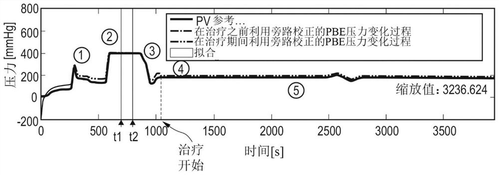
[0052] figure 1 An example of a pressure profile in millimeters of mercury (mmHg) is shown for a pressure sensor (here a PBE pressure sensor, which is explained in more detail below), where time t is in seconds (s).

[0053] In phase 1, the tube is inserted and filled with fluid into two clamping devices, at least one pressure sensor is integrated into each of the two clamping devices and the pressure is measured in the form of a force signal at the dialysis machine . The tubing system is filled by varying the flow pump speed of at least one pump. During this phase, the machines and pipes are also leak tested.

[0054] In phase 2, the pressure in the tube is kept constant. After a brief stabilization phase, already described step a) is performed for regression analysis and prediction of at least one correction function for finding a correction signal for correcting the drift signal using the corresponding pressure reference signal. In step a), th...

no. 2 approach

[0124] The second embodiment is similar to the first embodiment, so only the differences from the first embodiment are explained below.

[0125] The reference pressure measurement of the pressure signals PBE and PA in step c) (during treatment) can also be performed using the venous clamp SAKV and the arterial clamp SAKA as an alternative to the method described in the first embodiment.

[0126] To this end, as in the exemplary first configuration, the dialyzer flow is switched to a bypass and the tube clamps SAKV and SAKA are closed. Forms a pressure-tight connection in the tube. Stop the blood pump BP. However, due to the delay, the blood pump BP continues to rotate for a short time after it stops, so that the arterial part develops a negative pressure, and the venous part develops a positive pressure, and both have the same pressure ratio relative to each other over time . The PBE pressure signal is calibrated using a PV pressure reference sensor. The PA pressure signal...


PUM


Abstract

The invention relates to a method for calibrating a first pressure sensor (PA), which measures a first pressure in the form of a force signal within a hose (1) filled with liquid and which bears directly against the hose and is integrated into a first clamping fixture for the correction of a drift signal caused by the hose by a correction function with the aid of a pressure reference signal, which is acquired by a first pressure reference sensor (PHOP). The method comprises the following steps: a) recursive analysis and forecasting of at least one correction function for finding a correction signal for the correction of the drift signal with the aid of a corresponding pressure reference signal, which is measured by the first pressure reference sensor, at constant internal pressure and constant internal temperature in the hose; b) first calibration of the force signal measured by the first pressure sensor and corrected with the aid of the correction signal with the pressure reference signal, which is measured by the first pressure reference sensor, prior to an active use of the hose; and c) second calibration of the force signal measured by the first pressure sensor and corrected with the aid of the correction signal with the pressure reference signal, which is measured by a second pressure reference sensor (PV) during an active use of the hose. The invention further relates to a device designed for the application of a method of this kind.

Description

technical field [0001] The present disclosure relates to a method and a device for calibrating pressure measurements or force sensor measurements for determining the internal tube pressure in an extracorporeal circuit for use in direct application to The measured value determined from the pressure measurement is corrected with the correction signal when / adjacent / adjacent to the force sensor of the filling tube. Background technique [0002] In general, the internal pipe pressure can be measured by means of a pressure measuring line. The (first) tube whose internal pressure is to be measured is connected to a pressure measurement line (second tube) which in turn feeds the pressure to be measured to a (piezoelectric) pressure sensor / pressure transducer. For this, the pressure measuring line is connected to the (first) pipe via a T-piece. The pressure sensor is preferably arranged at the upper (free) end of the pressure measurement line with a Luer lock connection. Between t...

Claims


Application Information

Patent Timeline
Patent Type & Authority Applications(China)
IPC IPC(8): A61M1/16A61M1/36
CPCA61M1/1621A61M1/1605A61M1/3639A61M2205/3331G01L27/002G01L9/0001
Inventor 法赫·艾哈迈德希尔维·克劳斯亨里克·沃尔夫托比亚斯·沃施密特
Owner B BRAUN AVITUM
Why Eureka
Try Eureka