
Packaging structure and measuring conduit

A technology for packaging structures and measuring catheters, applied in catheters, cardiac catheters, measuring devices, etc.

Inactive Publication Date: 2022-02-11
HANGZHOU WEIMING XINKE TECH CO LTD +1
View PDF11 Cites 0 Cited by
  • Summary
  • Abstract
  • Description
  • Claims
  • Application Information

AI Technical Summary

Problems solved by technology

[0007] The object of the invention is to at least solve the problem of stable packaging of sensors

Method used


Image

  • Packaging structure and measuring conduit
  • Packaging structure and measuring conduit
  • Packaging structure and measuring conduit

Examples


Embodiment 1

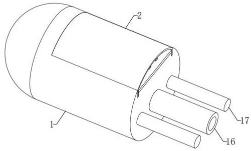
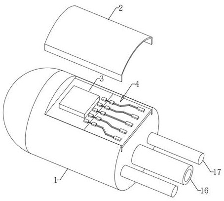
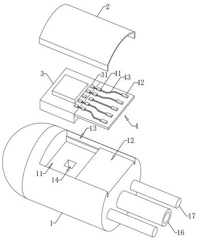
[0042] Such as figure 1 , figure 2As shown, a package structure of this embodiment includes: a base 1 with a receiving groove, a cover plate 2 for covering the opening of the receiving groove, a pressure sensor 3 embedded in the bottom of the receiving groove, and a welding wire plate 4. The base 1 and the cover plate 2 can be made of biocompatible materials such as stainless steel, titanium alloy, or polytetrafluoroethylene by injection molding or machining. Both the base 1 and the cover 2 are made of rigid materials, so the external stress will not be transmitted to the sensing surface of the sensor. At the same time, because the base 1 and the cover 2 also improve the sealing of the overall package, the sensor Measurement reliability.

[0043] Such as image 3 As shown, the base 1 is a cylindrical structure whose two ends are respectively a spherical end and a plane end, and the receiving groove communicates with the plane end of the base 1 . A third embedding groove ...

Embodiment 2

[0057] Such as image 3 , Figure 4 As shown, a connecting pipe 16 connected to a through hole 15 and two connecting rods 17 are arranged on the end face of the plane end of the base 1 , and the two connecting rods 17 are symmetrically distributed on both sides of the connecting pipe 16 . The connecting pipe 16 and the connecting rod 17 can be fixedly connected to the base 1 , or integrally formed with the base 1 . The connecting rod 17 is a round rod, and the axial directions of the connecting pipe 16 and the connecting rod 17 are parallel to the axial direction of the base 1 .

[0058] Such as Figure 4 , Figure 5 As shown, a measuring catheter in this embodiment includes: a base 1 , a catheter body 6 connected to the base 1 , and an enameled wire 5 connected between the base 1 and the catheter body 6 . The enameled wire 5 can use conductors and insulation, such as copper, aluminum and polyester, etc., and is made by setting out, annealing, painting, baking, cooling, lu...


PUM


Abstract

The invention relates to a packaging structure and a measuring catheter, and belongs to the field of implantable medical instruments. The packaging structure comprises: a base, wherein the base is a cylinder with one spherical end, a containing groove is formed in the base, and a hole with the two ends communicated with the spherical end of the base and the containing groove respectively is further formed in the base; a pressure sensor fixedly arranged in the containing groove, wherein a pressure sensing hole is formed in the pressure sensor, and is communicated with the hole of the base; the hole of the base, wherein the hole of the base provides a conduction path for pressure, so that the sensing surface of the sensor is isolated from a welding sealing surface, the sensing surface of the sensor is protected, the reliability and the stability of sensor measurement are ensured, the sealing performance of the sensor is improved, and the difficulty of a sealing waterproof process is reduced; a cover plate bonded in the containing groove, wherein the outer wall of the cover plate is flush with the peripheral surface of the base; and a sealant filled in a cavity between the containing groove and the cover plate. The packaging structure has the effect of stably packaging the sensor.

Description

technical field [0001] The invention relates to the technical field of implantable medical devices, in particular to a packaging structure and a measuring catheter with the packaging structure. Background technique [0002] This section provides background information related to the present disclosure only and is not necessarily prior art. [0003] Invasive pressure measurement is an important measurement method for monitoring the internal pressure of the human body in clinical applications. In clinical applications, invasive manometry catheters are often used to monitor internal pressures such as arterial blood pressure, central venous pressure, and intracranial pressure. [0004] At present, the measurement principle commonly used in the pressure measurement catheters on the market is that the catheter is first placed in the blood vessel of the measured site through puncture, the proximal end of the catheter is connected to the pressure sensor, and the catheter is perfused...

Claims


Application Information

Patent Timeline
IPC IPC(8): G01L19/14A61B5/0215A61M25/00
CPCG01L19/149G01L19/143G01L19/144A61B5/0215A61M25/0043A61M25/0021A61B2562/0247A61M2025/0002
Inventor 余容英章泽波高猛叶乐
Owner HANGZHOU WEIMING XINKE TECH CO LTD
Learn More