Circularly polarized millimeter wave lens antenna device

A lens antenna, millimeter wave technology, applied in antennas, resonant antennas, electrical short antennas, etc., can solve the problems of large thickness of dielectric lens, large loss of copper foil, narrow beam, etc., and achieve easy industrial production, low manufacturing cost, and improved performance effect

Pending Publication Date: 2022-03-04
广州合智瑞达科技有限公司
View PDF2 Cites 0 Cited by
  • Summary
  • Abstract
  • Description
  • Claims
  • Application Information

AI Technical Summary

Problems solved by technology

[0002] In complex environments, in order to improve radar measurement accuracy and distinguish multipath frequency components and other target interference frequency components, in addition to using more complex radar signal processing algorithms, the following measures can be used to improve the antenna: narrow the antenna beam, Improve the spatial resolution of the radar system; increase the antenna gain, improve the carrier-to-noise ratio of the signal; improve the antenna impedance and gain bandwidth, allow wider sweep bandwidth, improve distance resolution; use circularly polarized antennas, polarization isolation , to improve the anti-multipath interference capability of the radar system; however, in the millimeter-wave frequency band, using the traditional microstrip array antenna method, the loss of the printed medium board medium and copper foil is large, and it is difficult to achieve high gain; the sidelobe suppression of the beam requires high processing accuracy ;The larger the antenna array, the narrower the gain and impedance bandwidth, which is not conducive to the increase of the sweep bandwidth; the design of the feed network for circularly polarized antenna arrays is complex; the high gain and narrow beam require the size of the printed medium board to double, resulting in cost rise;
[0003] The authorized announcements are CN104701633A and CN109768374A patents disclose the method of using a dielectric lens to achieve high gain, broadband and narrow beam, but the thickness of the dielectric lens is too large, which is not conducive to the mass production of the mold opening injection molding process to reduce costs, and it is inconvenient to combine with other active Circuit integration, circular polarization is not achieved

Method used


Image

  • Circularly polarized millimeter wave lens antenna device
  • Circularly polarized millimeter wave lens antenna device
  • Circularly polarized millimeter wave lens antenna device

Examples


Embodiment 1

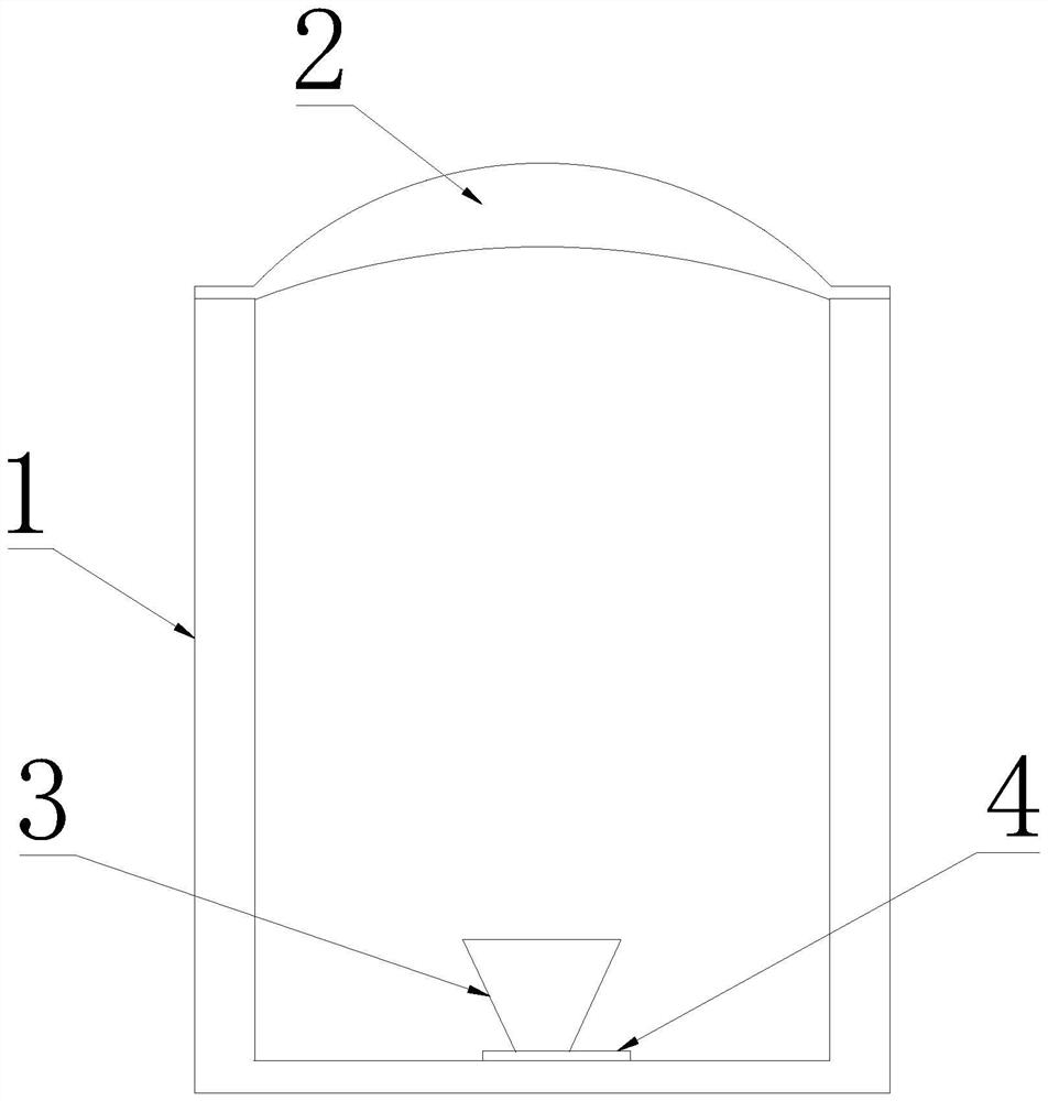
[0032] Such as Figure 1-3 As shown, a circularly polarized millimeter-wave lens antenna device proposed by the present invention includes a base 1, a dielectric lens 2, a horn antenna 3 and a feed 4;

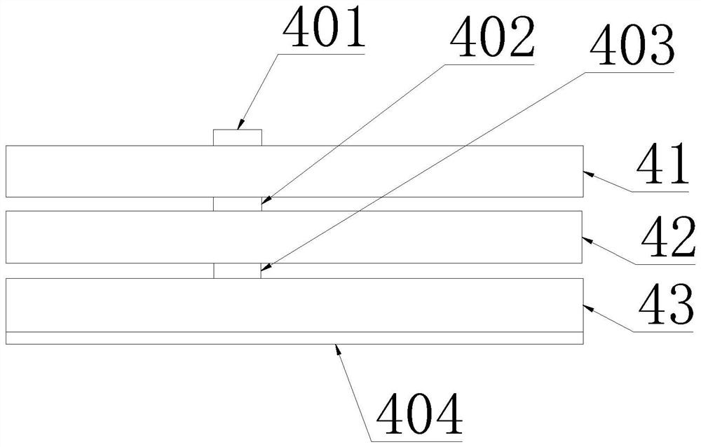
[0033] The feed source 4 includes a dielectric board A41, a dielectric board B42 and a dielectric board C43; the dielectric board A41, the dielectric board B42 and the dielectric board C43 are stacked and connected sequentially; the upper end surface of the dielectric board A41, between the dielectric board A41 and the dielectric board B42, and A first layer of copper foil 401, a second layer of copper foil 402, a third layer of copper foil 403 and a fourth layer of copper foil 404 are provided between B42 and the dielectric board C43 and on the lower end surface of the dielectric board C43;

[0034] Wherein, the thickness of the first layer of copper foil 401 and the fourth layer of copper foil 404 is 35 μm; the thickness of the second layer of copper foil 402 and the third la...

Embodiment 2

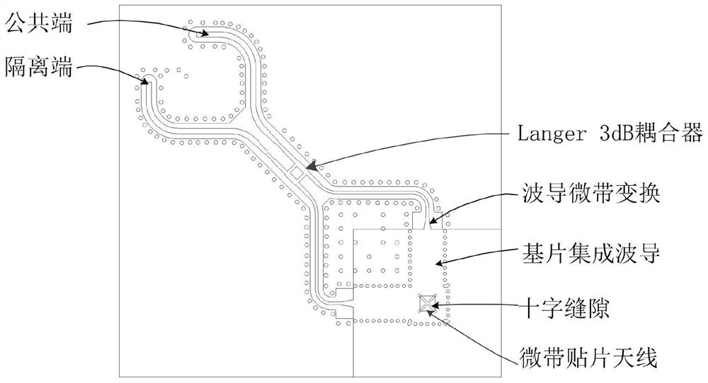
[0056] Such as Figure 4-6 As shown, the application of a circularly polarized millimeter-wave lens antenna device proposed by the present invention includes the circularly polarized millimeter-wave lens antenna device in Embodiment 1, and the circularly polarized millimeter-wave lens antenna device is applied in the wave frequency band of 79 GHz Carry out electromagnetic wave signal transmission and reception;

[0057] Then, the center frequency is 79GHz;

[0058] Bandwidth: ≥7GHz;

[0059] Gain: ≥25dB;

[0060] 3dB beamwidth: ≤±3°;

[0061] Standing wave ratio: ≤2;

[0062] Side lobe suppression ≥: 20dB;

[0063] Axial ratio: ≤1dB.


PUM


Abstract

The invention relates to the field of millimeter wave antennas, in particular to a circularly polarized millimeter wave lens antenna device which comprises a base, a dielectric lens, a horn antenna and a feed source. The feed source is provided with a first layer of copper foil, a second layer of copper foil, a third layer of copper foil and a fourth layer of copper foil; a microstrip patch antenna is arranged on the first layer of copper foil; a square hole is formed in the second layer of copper foil; the third layer of copper foil, the fourth layer of copper foil, the dielectric plate C and the metalized blind hole array form an L-shaped substrate integrated waveguide; two orthogonal gaps are formed in the third layer of copper foil; a Langer3dB coupler is arranged on the fourth layer of copper foil, and a 0-degree / 90-degree port of the Langer3dB coupler is connected with the two ends of the L-shaped substrate integrated waveguide; the dielectric lens is connected with the base; the horn antenna is connected with the dielectric plate A; circular polarization, high gain, narrow beam, low sidelobe and wide band of the antenna can be realized so as to improve the performance of a radar system.

Description

technical field [0001] The invention relates to the field of millimeter wave antennas, in particular to a circularly polarized millimeter wave lens antenna device. Background technique [0002] In complex environments, in order to improve radar measurement accuracy and distinguish multipath frequency components and other target interference frequency components, in addition to using more complex radar signal processing algorithms, the following measures can be used to improve the antenna: narrow the antenna beam, Improve the spatial resolution of the radar system; increase the antenna gain, improve the carrier-to-noise ratio of the signal; improve the antenna impedance and gain bandwidth, allow wider sweep bandwidth, improve distance resolution; use circularly polarized antennas, polarization isolation , to improve the anti-multipath interference capability of the radar system; however, in the millimeter-wave frequency band, using the traditional microstrip array antenna met...

Claims


Application Information

Patent Timeline
Patent Type & Authority Applications(China)
IPC IPC(8): H01Q1/50H01Q15/02H01Q13/02H01Q1/38H01Q9/04
CPCH01Q1/50H01Q15/02H01Q13/0241H01Q13/106H01Q9/0428
Inventor 梁卫祖刘培育陈侃
Owner 广州合智瑞达科技有限公司
Why Eureka
Try Eureka