
Vibration measurer with optical fibre detector

A technology of vibration measurement and optical fiber, which is applied to vibration measurement in solids, measurement devices, and vibration measurement, etc. It can solve problems such as low sensitivity, small dynamic range of amplitude, and large distortion, and achieve fast response to light intensity changes and dynamic range. large, distortion-reducing effect

Inactive Publication Date: 2004-03-10
胜利油田天勤投资咨询有限责任公司
View PDF0 Cites 0 Cited by
  • Summary
  • Abstract
  • Description
  • Claims
  • Application Information

AI Technical Summary

Problems solved by technology

[0002] The amplitude and frequency of vibration are the two main parameters for measuring vibration. Currently, commonly used vibration measuring devices use the electromotive force generated by measuring coils moving in a magnetic field to judge the structure of vibration. Due to the uneven distribution of the magnetic field itself, it is difficult to Therefore, the frequency band for measuring vibration is not wide enough, the dynamic range of amplitude is small, and the distortion is large, especially when measuring weak vibration signals, the sensitivity is low, which limits the application field of current vibration measurement devices.

Method used


Image

  • Vibration measurer with optical fibre detector
  • Vibration measurer with optical fibre detector
  • Vibration measurer with optical fibre detector

Examples


Embodiment Construction

[0024] Below in conjunction with accompanying drawing and by embodiment the present invention is further described:

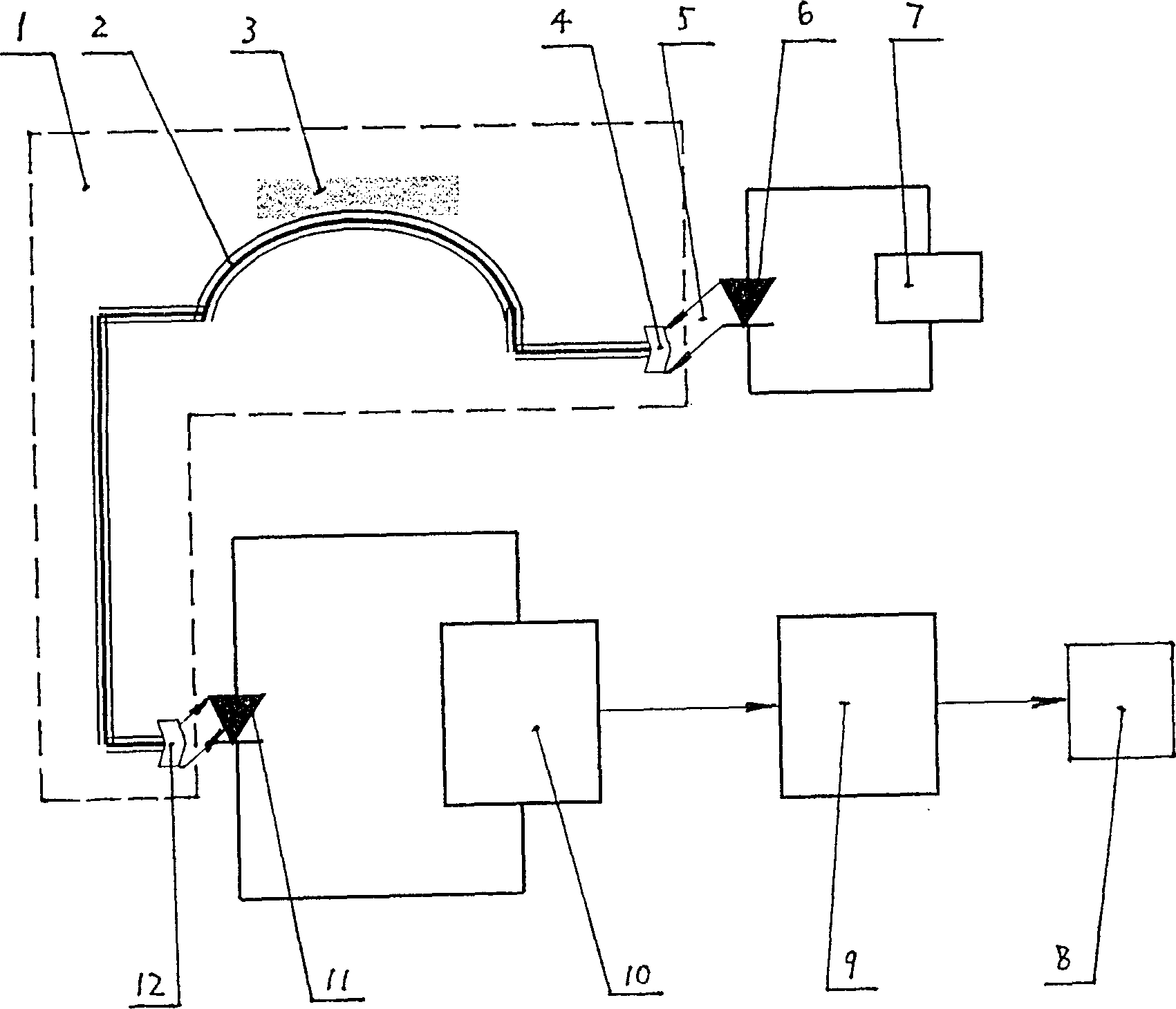
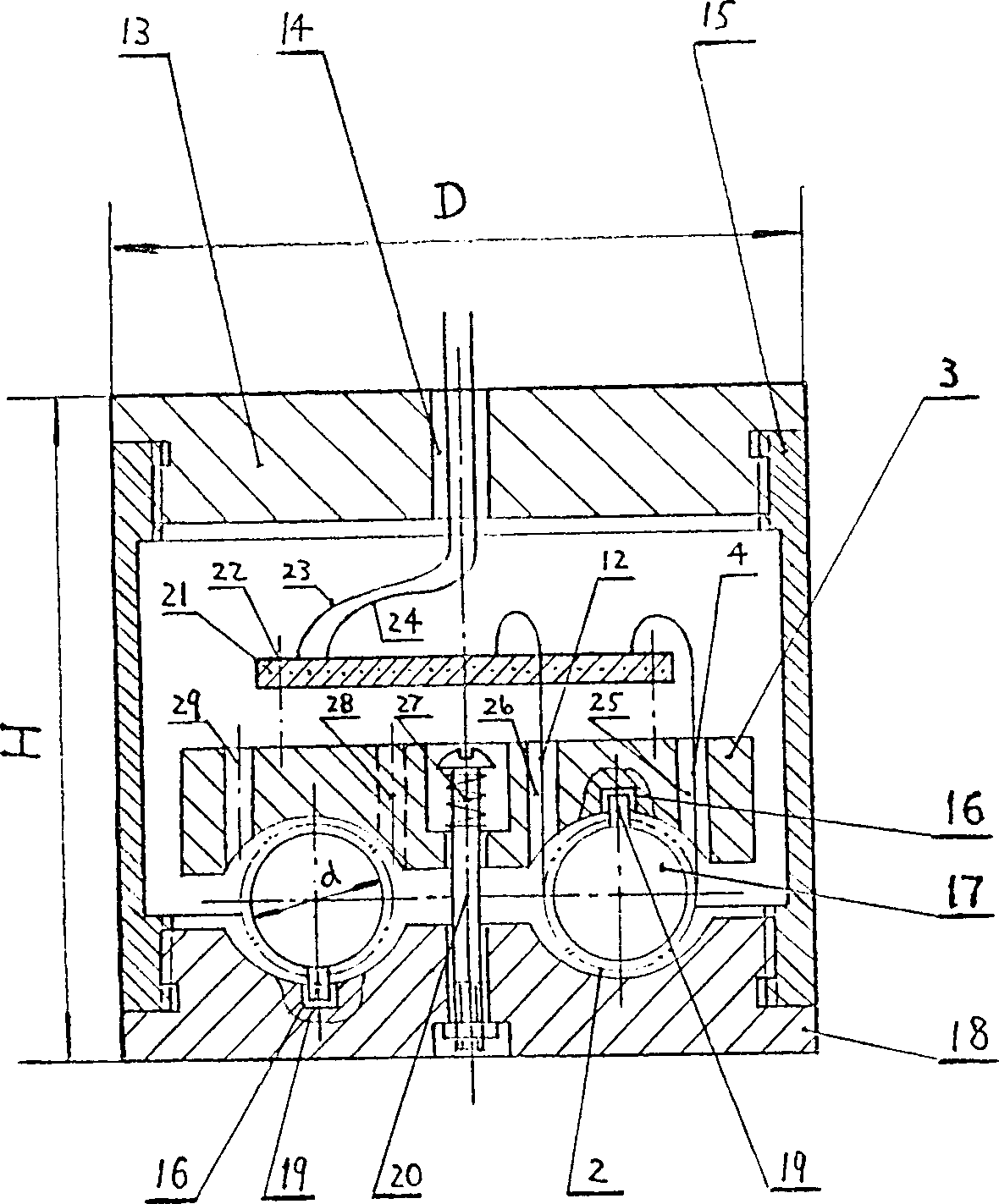
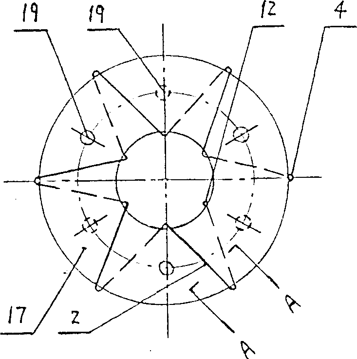
[0025] figure 1 The vibration measuring device shown includes a light emitting diode 6, a photodiode 11, a voltage amplifier 9 and a drive output 8, and is characterized in that: a light emitting diode circuit composed of a light emitting diode and a constant current source circuit 7 is composed of a photodiode and a current-voltage conversion The device 10 forms a light intensity current converter, a current voltage converter, a voltage amplifier, and a drive output are connected in series in sequence, and there is another optical fiber detector 1. In this detector, the input end of the optical fiber 2 wound on the support passes through its The inlet interface 4 is directly connected with the light-emitting diode, and the optical fiber outlet is directly connected with the photosensitive diode through its outlet interface 12, and the base 18 ( figure 2 show...


PUM


Abstract

The invention relates to a device for measuring vibration that belongs to an area of physical measuring instrument. The device includes an optical fiber detector whose entering ends is wrapped on a supported and is connected to light emit diode and the leaving end is connected to a light sensitive diode directly. The bottom base is connected to inductor and the optical fiber is clamped between the base and the inductor. There are heaves on the top part and bottom part of the supporter, and grooves on the relevant part of the bottom base and the inductor. The invented device provides features of wider frequency band, larger dynamic range of amplitude, small distortion, and high sensitivity so as to expend the area for measuring vibration.

Description

technical field [0001] The invention relates to a vibration measuring device, in particular to a vibration measuring device with an optical fiber detector, and relates to the field of physical measuring instruments. Background technique [0002] The amplitude and frequency of vibration are the two main parameters for measuring vibration. Currently, commonly used vibration measuring devices use the electromotive force generated by measuring coils moving in a magnetic field to judge the structure of vibration. Due to the uneven distribution of the magnetic field itself, it is difficult to Therefore, the frequency band for measuring vibration is not wide enough, the dynamic range of amplitude is small, and the distortion is large, especially when measuring weak vibration signals, the sensitivity is low, which limits the application field of the current vibration measurement device. Contents of the invention [0003] The present invention provides a vibration measuring device,...

Claims


Application Information

Patent Timeline
Patent Type & Authority Patents(China)
IPC IPC(8): G01H1/00G01H9/00G01N1/00
Inventor 谭成忠张建敏郑景翔
Owner 胜利油田天勤投资咨询有限责任公司
Learn More