
Stator structure of magnetic suspension magnetic flux switching motor

A magnetic flux switching motor and stator structure technology, applied in the direction of magnetic circuit shape/style/structure, winding conductor shape/style/structure, magnetic attraction or thrust holding device, etc., can solve unfavorable industrialization, cold end Large space, damage to the stator core structure of the motor, etc., to achieve the effects of convenient processing and assembly, high stator slot filling rate, and high power density

Pending Publication Date: 2022-03-08
SOUTHEAST UNIV
View PDF2 Cites 0 Cited by
  • Summary
  • Abstract
  • Description
  • Claims
  • Application Information

AI Technical Summary

Problems solved by technology

However, the heat dissipation technology of the stator cooling circuit is usually unable to cool the end of the stator winding, which will lead to a high temperature area at the end of the winding; the oil injection cooling heat dissipation technology requires the design of complex oil nozzles and circulation circuits; It is more common in electromechanical motors. The refrigerant needs a special recycling device. When using a heat pipe, the cold end and the hot end need to be scientifically designed and arranged. The cooling effect is related to the space position and gravity distribution of the motor. In addition, the space occupied by the cold end is also bigger
[0005] In order to improve the heat dissipation at the end of the stator winding, the existing technology mainly includes two methods: the first method is a forced air cooling method that makes the cold air contact with all the heating parts of the generator as much as possible. This method requires complex Fan structure and air path design; the second way is to open radial ventilation holes, holes, and channels in the stator, which means that the structure of the stator core of the motor will inevitably be damaged, which will affect the electromagnetic performance of the motor. The cooling method is conventional forced wind Cold or liquid cooling in the pipeline, further increase in motor processing cost and complexity, and increased structural unreliability, which is not conducive to actual industrialization

Method used


Image

  • Stator structure of magnetic suspension magnetic flux switching motor
  • Stator structure of magnetic suspension magnetic flux switching motor
  • Stator structure of magnetic suspension magnetic flux switching motor

Examples


specific Embodiment 1

[0041] Specific embodiment 1: The stator structure of the magnetic levitation flux switching motor integrated with the cooling module at the end of the winding and the radial magnetic bridge

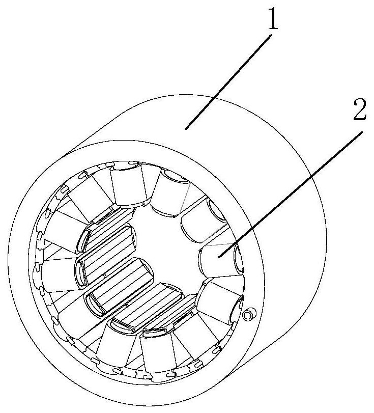
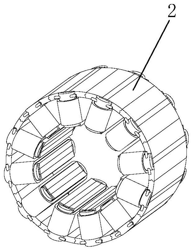
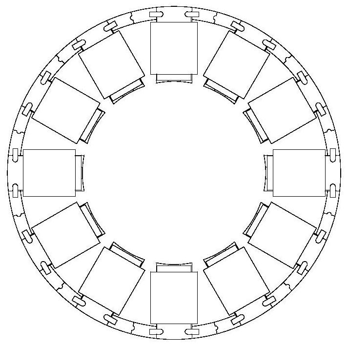
[0042] Such as figure 1 , figure 2 with image 3 As shown, this embodiment provides a highly integrated, high-efficiency heat dissipation type magnetic levitation flux switching motor stator structure, including a motor casing 1 and a stator 2 . The motor casing 1 is usually shrunk on the outside of the stator 2 , and its axial length is generally longer than that of the stator 2 . In the motor casing 1, there are generally axial or radial spiral type, return type and other water channels according to the cooling needs. Based on the principles of science and fluid-solid coupling, the water channel type with better cooling effect is designed.

[0043] The stator has a modular structure, which is beneficial to the processing and assembly of the stator, while ensuring a high stator slo...

specific Embodiment 2

[0058] Specific embodiment 2: Stator structure of a magnetic levitation flux switching motor integrated with a cooling module at the end of the winding and two sets of windings

[0059] Such as Figure 11 , Figure 12 with Figure 13 As shown, for the stator structure of the bearingless flux switching motor provided in this embodiment, the front side magnetic pole bypass and the rear side magnetic pole bypass in the specific embodiment 1 will no longer be set in the bearingless magnetic flux switching motor, so the module The two ends of the optimized stator will only be provided with the front side winding end heat dissipation module 3 and the rear side winding end heat dissipation module 4, and the stator winding 208 in the specific embodiment 1 will be replaced by two sets of windings, that is, the torque winding 6 and the suspension winding 6. Force winding 7.

[0060] Specific embodiment 2 is consistent with the structure and cooling medium passage of the front side wi...


PUM


Abstract

The invention discloses a stator structure of a magnetic suspension flux switching motor, and belongs to the technical field of power generation, power transformation or power distribution. Comprising a stator with a modular structure and a motor shell, wherein the modularized stator consists of a front side winding end part heat dissipation module, a rear side winding end part heat dissipation module, a modularized stator left wing, a modularized stator permanent magnet, a modularized stator right wing, a front side magnetic conductive column left wing, a front side magnetic conductive column permanent magnet, a front side magnetic conductive column right wing, an insulating layer, a stator winding, a rear side magnetic conductive column right wing and a rear side magnetic conductive column permanent magnet; and the rear side magnetic conductive column left wing is formed. The front side winding end portion heat dissipation module and the rear side winding end portion heat dissipation module are of a hollow structure and are symmetrically provided with a cooling medium inlet and a cooling medium outlet, a cooling medium channel is arranged in a hollow cavity, one side of the heat dissipation module is a smooth curved surface, and good thermal contact can be achieved between the heat dissipation module and a stator winding and between the heat dissipation module and an insulator. The magnetic suspension flux switching motor has the remarkable technical advantages of high integration and efficient heat dissipation, and has important theoretical and practical significance for achieving industrial application of the magnetic suspension flux switching motor.

Description

technical field [0001] The invention relates to electrical and mechanical transmission technology, specifically discloses a stator structure of a magnetic levitation flux switching motor, and belongs to the technical field of power generation, transformation or distribution. Background technique [0002] At present, flux switching motors have been extensively researched and applied in the fields of industrial drive, cordless elevator traction, tidal and wind power generation, etc. . In recent years, with the development of high-speed motor technology, the types of high-speed motor products have gradually become more abundant. Flux switching motors using magnetic suspension bearings can greatly improve or overcome the problems of loss, heat dissipation and stress faced by traditional rotor permanent magnet motors. It shows great structural advantages and application potential. [0003] Technological innovation and product development have been carried out around bearingless...

Claims


Application Information

Patent Timeline
IPC IPC(8): H02K9/19H02K5/20H02K3/24H02K1/17H02K3/28H02K3/52H02K1/14H02K1/18H02N15/00
CPCH02K9/19H02K5/203H02K3/24H02K1/17H02K3/28H02K3/522H02K1/146H02K1/18H02N15/00
Inventor 花为张志恒于雯斐王培欣
Owner SOUTHEAST UNIV
Learn More