Processing method for one-step forming of continuous fiber reinforced composite pipe

A continuous fiber, reinforced composite technology, applied in the field of one-step forming of continuous fiber reinforced composite pipes, can solve the problems of insufficient interlaminar shear strength, weak interlaminar bonding force, insufficient shear strength, etc. The effect of poor adhesion between the two, ensuring uniformity and compatibility, and improving shear strength performance

Active Publication Date: 2022-03-11
YONGGAO CO LTD
View PDF10 Cites 0 Cited by
  • Summary
  • Abstract
  • Description
  • Claims
  • Application Information

AI Technical Summary

Problems solved by technology

Such as the Chinese patent document (publication number: CN109664479A) discloses a plastic pipe forming assembly line. The composite pipe produced by this manufacturing process needs to be wound in multiple layers to ensure that the prepared pipe reaches the required strength. However, the thickness of the continuous fiber is very large. Small, the bonding layer formed by direct winding on the surface of the inner tube is very small. At the same time, the winding of each layer of fibers in turn often results in limited or no bonding in the contact area between the fibers, resulting in poor bonding between layers. Strong, the delamination between the layers is obvious, resulting in insufficient shear strength between the layers, easy to cause damage to the pipeline during use
Another example is the continuous fiber-reinforced thermoplastic pipe and production method disclosed in the Chinese patent document (notification number: CN105003753B). The inner layer is formed by wrapping the thermoplastic film or sheet evenly on the metal mandrel in a winding or longitudinal manner. Then weave or wind the fiber pre-impregnated with thermoplastic material on the inner layer or longitudinally on the surface of the inner layer, enter the mold cavity under the action of the tractor to heat, reach the predetermined temperature, melt the thermoplastic material, and use it on the side The extruder pressurizes and extrudes the supplementary material to integrate the three-layer structure into one, and forms a thermoplastic protective layer on the surface, and then sizing, cooling and shaping, cutting and other processes to obtain the final pipe, which still requires the inner layer first , the inner layer and the thermoplastic material in the mold are not formed synchronously, and there will also be problems of weak bonding between layers, and insufficient shear strength between layers

Method used


Image

  • Processing method for one-step forming of continuous fiber reinforced composite pipe
  • Processing method for one-step forming of continuous fiber reinforced composite pipe
  • Processing method for one-step forming of continuous fiber reinforced composite pipe

Examples


Embodiment 1

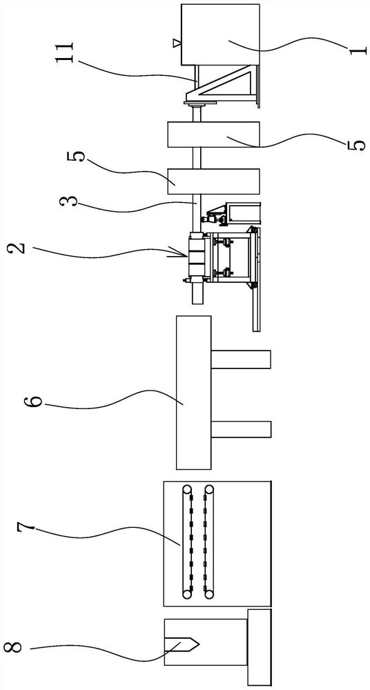
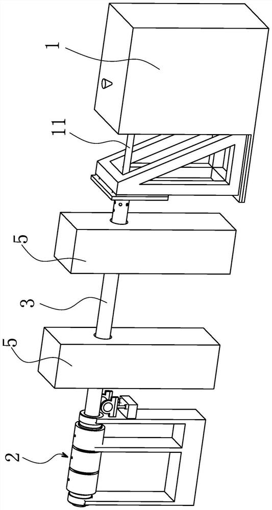
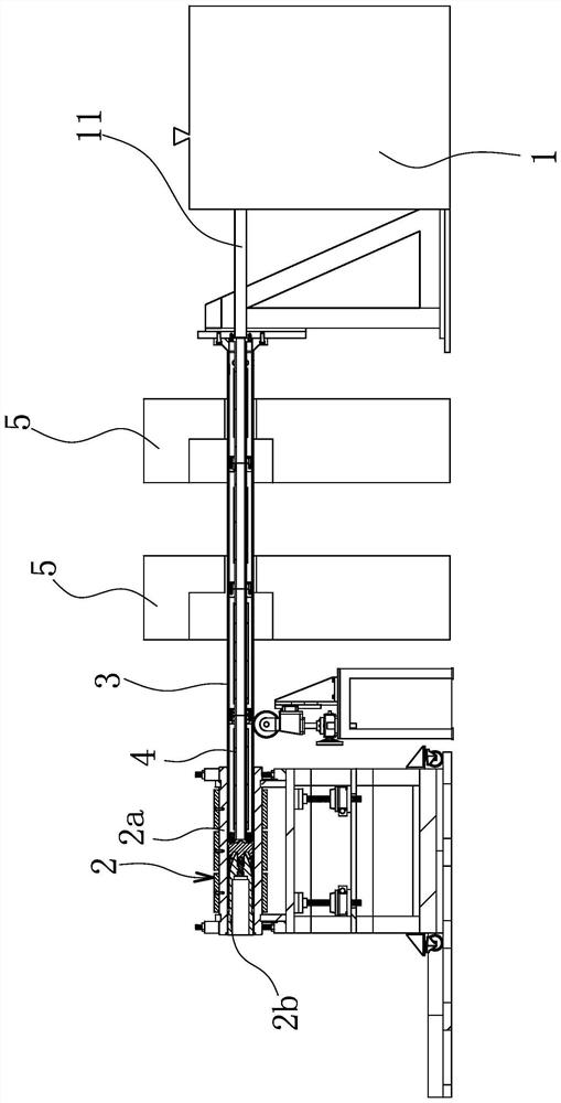
[0030] combine Figure 1-2 As shown, the production line of the one-step forming method of continuous fiber reinforced composite pipe can be a continuous processing including extruder 1, forming mold 2, winding machine 5, vacuum calibrating box 6, tractor 7 and pipe cutting machine 8, etc. Production line for composite pipes. More specifically, combining image 3 and Figure 4 A mold cavity 2c is formed between the outer mold cover 2a of the above-mentioned forming mold 2 and the core mold 2b. This molding equipment also includes an outer tube 3 and a core tube 4. One end of the outer tube 3 is connected by the front port 2a1 of the outer mold cover 2a. Extending into the outer mold casing 2a, an annular cavity 2d is formed between the outer peripheral wall of the outer tube 3 and the inner peripheral wall of the outer mold casing 2a for the reinforcement fiber to pass through, and the mold cavity 2c is provided with a tube sleeved outside the core mold 2b. Cylindrical supp...

Embodiment 2

[0044] The production line mentioned in Embodiment 1 can be used to enter the pipeline production. Under the traction force of the tractor 7, the continuous glass fiber on one of the winding machines 5 is drawn to the outer peripheral surface of the outer pipe 3, and the winding is carried out by pulling A number of continuous fibers distributed along the axial direction of the outer tube 3 on the machine 5, so that the formed axial fiber lines are directly wrapped on the circumferential surface of the outer tube 3 to form an axial fiber layer into a tubular shape, and then pulled by another winding machine 5. The upper fibers are synchronously formed on the outer surface of the axial fiber layer along the fiber lines wound in the circumferential direction of the outer tube 3 outside the axial fiber layer to form a wound fiber layer, which may be a wound fiber layer formed in a 45° cross weaving manner, The above-mentioned axial fiber layer and winding fiber layer together form...


PUM

PropertyMeasurementUnit
Shear strengthaaaaaaaaaa

Abstract

The invention relates to a processing method for one-step forming of a continuous fiber reinforced composite pipe, and belongs to the technical field of composite pipeline processing. In order to solve the problem that multiple composite layers of an existing pipeline are prone to falling off, the one-step forming machining method of the continuous fiber reinforced composite pipe is provided and comprises the steps that the circumferential surface of an outer pipe is wrapped with a plurality of axial fiber layers formed by continuous fibers distributed in the axial direction of the outer pipe; a winding fiber layer which is wound along the circumferential direction of the outer pipe is wound outside the axial fiber layer to form a continuous reinforced fiber layer; the continuous fiber reinforced layer moves forwards in the axial direction of the outer pipe, enters a gap between the inner circumferential wall of an outer die sleeve of the forming die and the outer circumferential wall of the outer pipe and continuously passes through a die cavity; and the molten thermoplastic plastic material melt injected into the mold cavity and the continuous fiber reinforcement layer which continuously passes through are compounded to form a pipe blank, and the corresponding composite pipe is obtained after cooling. One-step processing can be realized, and the pipeline has the advantage of high shear strength.

Description

technical field [0001] The invention belongs to the technical field of composite pipe processing, and relates to a processing method for one-step forming of a continuous fiber reinforced composite pipe. Background technique [0002] With the continuous expansion of cities and the continuous extraction of oil and natural gas, the demand for transportation pipelines is also increasing. Traditional steel pipes have poor corrosion resistance and are not easy to handle, so they can no longer meet the current needs. At the same time, my country's main oil and natural gas are mostly distributed in deserts, swamps or mountainous areas, and the natural environment is relatively harsh. When laying steel pipelines, it is seriously affected by the natural environment, and due to ground subsidence, landslides and other reasons, the pipelines are extremely prone to damage. Phenomenon. Due to its low density, high strength, and excellent mechanical properties, such as good processing perf...

Claims


Application Information

Patent Timeline
IPC IPC(8): B29D23/00B29C48/09B29C48/355B29C70/34B29C70/38B29C70/52B29C70/54F16L9/14F16L57/02
CPCB29D23/00B29C70/384B29C70/34B29C70/523B29C70/545B29C48/09B29C48/355B29C48/0022F16L9/14F16L57/02
Inventor 黄剑汪鹏跃孙华丽陈卫丁杰钱杨
Owner YONGGAO CO LTD
Why Eureka
Try Eureka