Pressurizing vaporization device for recovering liquid oxygen cold energy and using method of pressurizing vaporization device
A vaporization device and liquid recovery technology, applied in liquefaction, refrigeration and liquefaction, energy input, etc., can solve the problems of waste of liquid oxygen cooling capacity, cold pollution of nearby environment, etc., and achieve the effect of reducing irreversible losses
- Summary
- Abstract
- Description
- Claims
- Application Information
AI Technical Summary
Problems solved by technology
Method used
Image
Examples
Embodiment 1
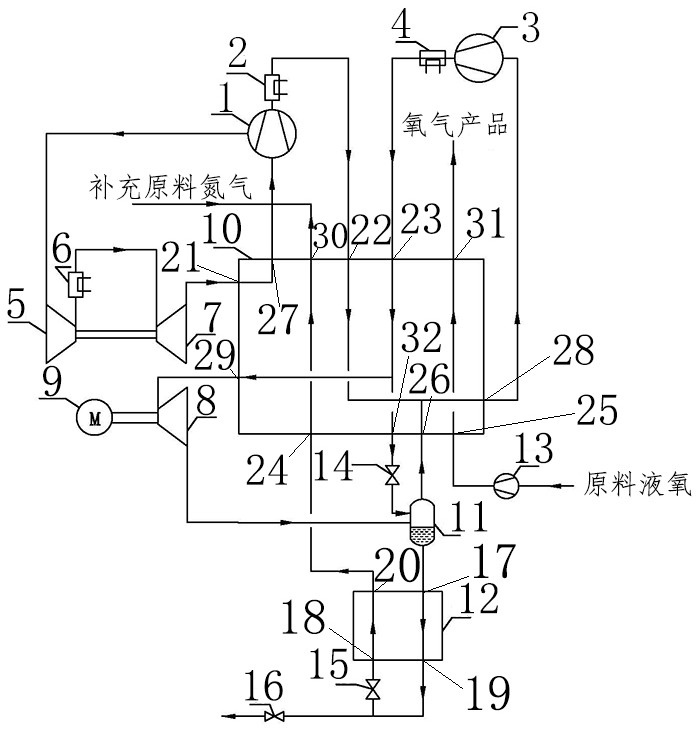
[0029] Such as figure 1 As shown: the raw material liquid oxygen is pressurized to about 8.4MPaG by the liquid oxygen pump 13 and then enters the fifth input end 25 of the heat exchanger 10, and is output from the fifth output end 31 of the heat exchanger 10 after being reheated by the heat exchanger 10 , the obtained product oxygen, the high-grade cold contained in the liquid oxygen is recovered in this process.
[0030] Nitrogen with a pressure of about 10KpaG (oxygen component is about 5ppm and nitrogen component is about 99.9%) enters the circulating nitrogen compressor 1 and is compressed and divided into two streams: one stream of nitrogen compressed to about 0.23MPaG is compressed from the first circulating nitrogen After pumping in the middle pumping section of machine 1, it enters the booster end 5 of the nitrogen booster expander to pressurize to a pressure of about 0.64MPaG, then enters the nitrogen booster expander, and then cools to about 313K in the cooler 6, and...
Embodiment 2
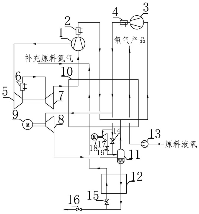
[0033] attached figure 2 Shown is a schematic diagram of a modified example of the device and method of the present invention. with attached figure 1 The difference is that the throttling valve 14 is considered to throttle the fluid, which has a large irreversible loss, and the liquid expander 17 connected in parallel with the throttle valve 14 can be used to expand the fluid output from the sixth output end of the cold end of the heat exchanger. At this time, the throttle valve 14 is closed or slightly opened. The liquid expander 17 is indirectly connected to the power generation brake end 18 through the gear box, and the power generation brake end 18 generates power externally. The valve 19 is used to adjust the pressure after the liquid expander 17 expands.
Embodiment 3
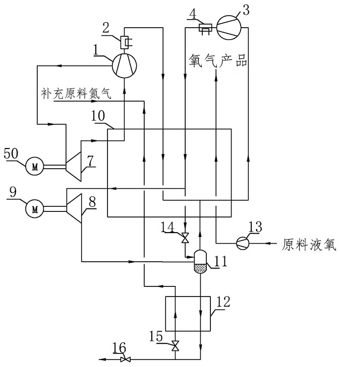
[0035] attached image 3 Shown is a schematic diagram of another modified example of the device and method of the present invention. with attached figure 1 The difference is that the nitrogen booster expander is composed of the nitrogen booster expander expansion end 7 and the nitrogen booster expander power generation braking end 50, and the two are indirectly connected through a gear box. Nitrogen with a pressure of about 10KpaG (the oxygen component is about 5ppm, and the nitrogen component is about 99.9%) enters the circulating nitrogen compressor 1 and is compressed and divided into two streams: one stream of nitrogen compressed to about 0.64MPaG is sent from the circulating nitrogen compressor 1 After being pumped in the middle pumping section, it directly enters the expansion port 7 of the nitrogen booster expander to expand to a pressure of about 25KpaG and a temperature of about 200K. The first output of the hot end is output, and the output temperature is about 310...
PUM
 Abstract
Description
Claims
Application Information
 - R&D
- Intellectual Property
- Life Sciences
- Materials
- Tech Scout
- Unparalleled Data Quality
- Higher Quality Content
- 60% Fewer Hallucinations
Browse by: Latest US Patents, China's latest patents, Technical Efficacy Thesaurus, Application Domain, Technology Topic, Popular Technical Reports.
© 2025 PatSnap. All rights reserved.Legal|Privacy policy|Modern Slavery Act Transparency Statement|Sitemap|About US| Contact US: help@patsnap.com


