Multi-laser radar detection system based on single laser light source

A laser light source and lidar technology, which is applied in the field of multi-lidar detection systems, can solve problems such as signal crosstalk, dynamic adjustment, and limit practical applications, and achieve the effects of avoiding coupling loss, stable power output, and reducing costs.

Pending Publication Date: 2022-03-25
SHANGHAI INST FOR ADVANCED STUDY OF ZHEJIANG UNIV
View PDF0 Cites 0 Cited by
  • Summary
  • Abstract
  • Description
  • Claims
  • Application Information

AI Technical Summary

Problems solved by technology

Moreover, it is impossible to dynamically adjust the detection distance or detection sensitivity by adjusting the output power of each laser radar.
Another solution is to use a single light source and detector to realize a multi-lidar system, but in this system, there is a lack of a power-adjustable beam splitter, and it is impossible to dynamically adjust the output optical power of each laser radar. In the system, the light is coupled from the space to the optical fiber, and then passed to the photodetector, which increases the coupling loss of the space light to the optical fiber
Moreover, the optical signals of different laser radars are converted into optical signals by using a unique photodetector, which is also prone to crosstalk between signals, which limits the practical application of this scheme.

Method used


Image

  • Multi-laser radar detection system based on single laser light source
  • Multi-laser radar detection system based on single laser light source
  • Multi-laser radar detection system based on single laser light source

Examples


Embodiment Construction

[0022] The present invention will be further elaborated below in conjunction with the accompanying drawings and embodiments.

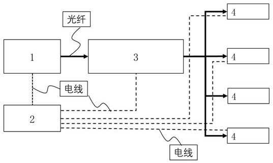
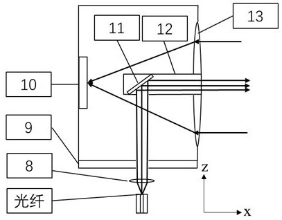
[0023] Multi-lidar detection systems such as figure 1 shown. The light source emitted by the laser light source 1 is coupled to the adjustable optical beam splitter 3 through the optical fiber, and then connected to multiple external light source laser radars 4 through the optical fiber. The reflected light signal detected by it passes through the built-in photodetector 11 ( image 3 , 4 ), it becomes an electrical signal and is transmitted to the controller 2 through the electrical signal transmission line. The controller 2 calculates the detection distance of the external laser radar 4 according to the pulse signal to the laser light source 1 and the feedback electric signal of the external light source laser radar 4 .

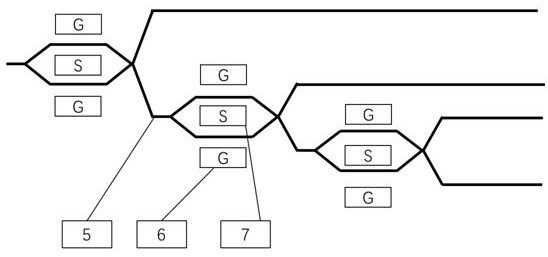
[0024] Dimmable beam splitters3, such as figure 2 As shown, a Mach-Zehnder-type interference structure based on a cascaded sp...


PUM


Abstract

The invention discloses a multi-laser radar detection system based on a single laser light source. The multi-laser radar detection system comprises a laser light source, an adjustable light beam splitter, an external light source laser radar and a controller, a light source emitted by the laser light source is coupled to the adjustable light beam splitter or the waveguide coupler through optical fibers and then connected to the multiple external light source laser radars through optical fibers, the external light source laser radars are provided with photoelectric detectors, detected reflected light signals are converted into electric signals, and the electric signals are fed back to the controller through electric signal transmission lines. The controller obtains a detection result according to a pulse signal of the laser light source and a feedback electric signal of the external light source laser radar. According to the invention, the output optical power of each laser can be dynamically adjusted, so that the detection distance and the detection sensitivity of each laser radar can be adjusted. The photoelectric detection module is integrated on the laser radar externally connected with the laser light source, so that coupling loss is avoided. The laser radar with an external laser light source and signal processing can reduce the cost of a single laser radar.

Description

technical field [0001] The invention belongs to the field of laser radar, and relates to a laser radar based on a single laser light source, an adjustable optical beam splitter, and multiple external light sources to realize multi-laser radar detection. Background technique [0002] The multi-lidar detection system is a combination of multiple independent laser radars, which can detect and perceive the surrounding environment more comprehensively, avoiding the blind spot of a single laser radar. The multi-lidar detection system has a wide range of applications in unmanned vehicles, surveying and mapping, monitoring and other fields. [0003] At present, one solution to realize a multi-lidar system is to use multiple independent single-line lidars or independent multi-line lidars to form a multi-lidar detection system. Such systems are expensive and expensive to maintain. Especially when a lidar fails, the entire lidar needs to be replaced. Moreover, it is impossible to dy...

Claims


Application Information

Patent Timeline
Patent Type & Authority Applications(China)
IPC IPC(8): G01S17/02G01S7/481
CPCG01S17/02G01S7/4817G01S7/4818
Inventor 黄强盛何赛灵
Owner SHANGHAI INST FOR ADVANCED STUDY OF ZHEJIANG UNIV
Why Eureka
Try Eureka