High-power multi-mode broadband rotary joint

A rotary joint, high-power technology, applied in electrical components, circuits, waveguide-type devices, etc., to achieve high power capacity, reduced wear, and wide operating frequency.

Active Publication Date: 2022-03-29
UNIV OF ELECTRONICS SCI & TECH OF CHINA
View PDF4 Cites 1 Cited by
  • Summary
  • Abstract
  • Description
  • Claims
  • Application Information

AI Technical Summary

Problems solved by technology

This rotary joint designed according to the characteristics of the working mode has a distinct mode selection feature and can only work in a single mode

Method used


Image

  • High-power multi-mode broadband rotary joint
  • High-power multi-mode broadband rotary joint
  • High-power multi-mode broadband rotary joint

Examples


Embodiment Construction

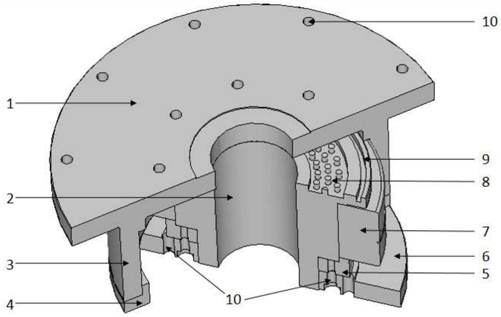
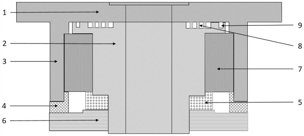
[0033] The specific implementation of the Ku-band non-contact high-power microwave rotary joint will be described below in conjunction with the accompanying drawings to meet the design goals of the Ku-band high-power gyro-traveling wave tube system.

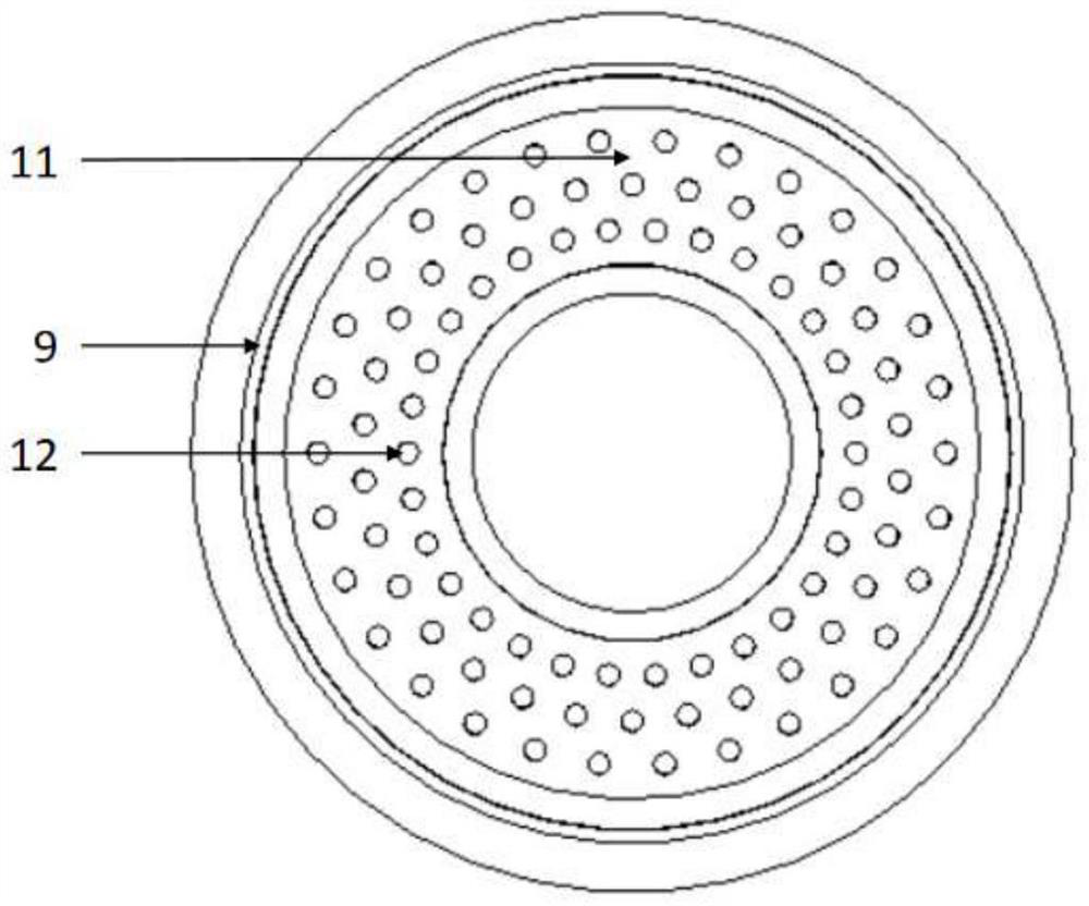
[0034] Such as figure 1 , figure 2 As shown, the high-power multimode broadband rotary joint includes a rotor circular waveguide 1, a stator circular waveguide 2, a gap waveguide choke structure 8, a choke coil structure 9 and a connection structure; the rotor circular waveguide 1 and the stator The circular waveguide 2 is an overmolded circular waveguide with the same caliber and coincident central axis, with a radius of 25 mm, and relative rotation is realized through a bearing structure; the gap waveguide choke structure 8 and the choke coil structure 9 are arranged on the rotor circular waveguide 1 and Adjacent end faces of the stator circular waveguide 2. The distance between the end faces is 0.1 mm, which ensures that th...


PUM


Abstract

The invention discloses a high-power multimode broadband microwave rotary joint, and belongs to the technical field of microwaves and millimeter waves. The rotary joint comprises a rotor circular waveguide, a stator circular waveguide and a bearing structure enabling the rotor circular waveguide and the stator circular waveguide to rotate relatively. The rotor circular waveguide and the stator circular waveguide are over-mode circular waveguides with the same aperture and superposed central axes, a certain distance exists between adjacent end faces, and a gap waveguide choking structure and a choking coil are arranged; the gap waveguide choke structure comprises an annular groove and a concentric ring array composed of metal cylinders. Through the combination of the gap waveguide structure and the choking coil, the field intensity at the joint of the rotary joint can be effectively reduced, high-efficiency transmission of microwaves can be realized within the range that the relative bandwidth exceeds 80%, and the advantages of high power capacity and low propagation loss are achieved; meanwhile, the rotary joint is compact in structure, belongs to a non-contact rotary joint, supports transmission of various circular waveguide modes in the rotary joint, and has longer service life.

Description

technical field [0001] The invention belongs to the field of microwave and millimeter wave technology, and in particular relates to a high-power multi-mode broadband microwave rotary joint. Background technique [0002] With the development of the national economy, microwaves are more and more widely used in high-power microwave weapons, super jammers, high-power radars, impact radars, high-energy radio frequency accelerators and plasma heating of controlled thermonuclear fusion. At the same time, with the continuous upgrading of functions, these systems put forward new requirements for the power source that generates microwaves, such as wider operating frequency band and higher power. At low frequencies, the device itself is larger. Even with fundamental mode operation, the device itself can realize the output of tens of millions of watts or even megawatts of power. Therefore, at low frequencies, most high power microwave sources use rectangular waveguide TE 10 mode or c...

Claims


Application Information

Patent Timeline
Patent Type & Authority Applications(China)
IPC IPC(8): H01P1/06
CPCH01P1/062
Inventor 吴泽威宋洪宇李泉立杨杰蒲友雷刘国王建勋罗勇
Owner UNIV OF ELECTRONICS SCI & TECH OF CHINA
Why Eureka
Try Eureka