Heavy metal tailing dry discharge system

A technology for heavy metals and tailings, which is applied in the sedimentation tank, the feeding/discharging device of the sedimentation tank, and the separation of sediments by centrifugal force.

Pending Publication Date: 2022-04-05
CHENGDU UNIVERSITY OF TECHNOLOGY
View PDF9 Cites 0 Cited by
  • Summary
  • Abstract
  • Description
  • Claims
  • Application Information

AI Technical Summary

Problems solved by technology

[0003] When thickening the tailings, after the ore feed of the thickener is mixed with the flocculant, it diffuses in the middle of the thickener to its surroundings, and then enters the pre-formed mud layer, and forms a mud layer together with the flocculant that enters the pulp at the same time, and It settles to the bottom layer of the thickener, and the liquid rises through the sediment layer, and the sediment layer acts as a filter, so that the fine particles cannot rise, and the slurry moves in the sediment layer, making the particles contact with the flocculant to continue to produce flocculation, and the rake arm Push the dense pulp to the bottom of the thickener, and then be discharged outside; when the existing thickener processes the pulp, the separation interface is easy to be unclear inside the thickener, and it is easy to run muddy, which leads to unsatisfactory concentration of the pulp

Method used


Image

  • Heavy metal tailing dry discharge system
  • Heavy metal tailing dry discharge system
  • Heavy metal tailing dry discharge system

Examples


Embodiment 1

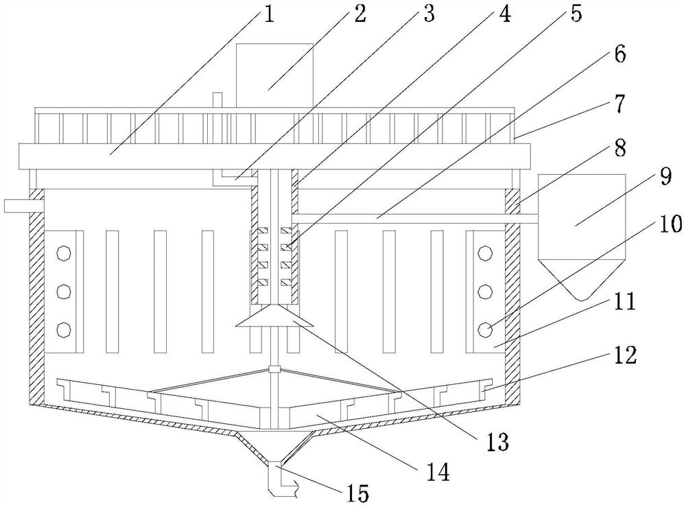
[0030] like Figures 1 to 3 As shown, this embodiment includes a tank body 8 with a tapered bottom, an operating table 1 is erected above the tank body 8, the motor 2 is upside down in the middle of the upper surface of the operating table 1, and the output end of the motor 2 is connected with a rotating shaft, The rotating shaft runs through the operation table 1 and extends to the bottom of the tank body 8 , and a rake arm 12 is arranged on the extension of the rotating shaft, an outer pipe 15 is arranged at the bottom of the tank body 8 , and a sleeve 4 is arranged at the bottom of the operation table 1 . , the sleeve 4 is sleeved on the upper section of the rotating shaft, the liquid outlet end of the cyclone 9 is communicated with the inner upper section of the sleeve 4 through the grouting pipe 6, and the operating table 1 is also provided with a liquid injection pipe that communicates with the inner upper section of the sleeve 4 3. A frustum 13 is provided on the outer ...

Embodiment 2

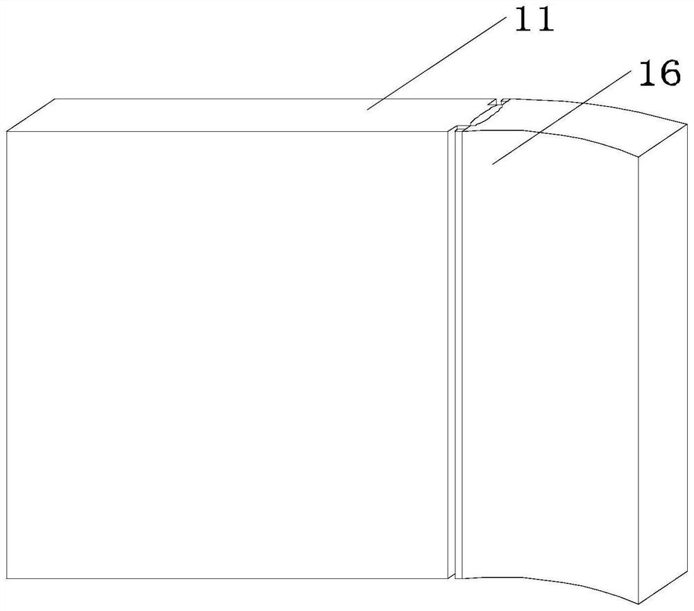
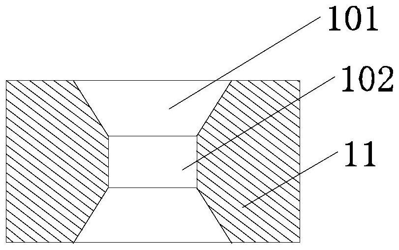
[0035] like Figures 1 to 3 As shown, this embodiment is based on Embodiment 1, and each of the baffles 11 is provided with a plurality of guide holes 10 , and the axis of the guide holes 10 is connected to the sleeve 4 . axis is vertical. The diversion hole 10 includes a through hole 102 and two expansion holes 101 communicating with both ends of the through hole 102 , and the inner diameter of the expansion holes 101 increases from the middle of the through hole 102 toward the side wall of the partition plate 11 .

[0036] When the rake arm 12 agitates the muddy layer at the bottom of the tank 8, the ore slurry above the muddy layer will generate a certain degree of eddy current. There is still a certain fluctuation in the area between the partitions 11. For this reason, in this technical solution, each partition 11 is provided with a plurality of diversion holes 10, so that the two adjacent buffer areas are partially connected, and Since the movement of the pulp in differ...

Embodiment 3

[0040] like Figures 1 to 3 As shown, this embodiment is based on Embodiment 1. In this embodiment, a plurality of annular plates 5 are arranged at intervals from top to bottom on the inner circumferential wall of the sleeve 4 along the axial direction of the sleeve 4, and the annular plates The inner diameter of 5 is larger than the diameter of the rotating shaft, and the grouting pipe 6 and the liquid injection pipe 3 are both located above the annular plate 5 . After the newly fed ore pulp is fed into the sleeve 4, a circulating flow is formed under the action of a plurality of annular plates 5, and after moving to the bottom of the sleeve 4, it contacts with the outer wall of the frustum 13, which also makes the ore pulp and the flocculant fully mixed, forcing The slurry spreads around in the horizontal direction to avoid impacting the sediment layer.

[0041] Preferably, an inner thread cylinder 14 that is threadedly matched is provided on the outer wall of the lower sec...


PUM


Abstract

The invention discloses a heavy metal tailing dry discharge system which comprises a tank body, a rake arm arranged on the extension of a rotating shaft, an outer discharge pipe arranged at the bottom of the tank body, a sleeve arranged at the bottom of an operation table, a liquid injection pipe arranged on the operation table, a frustum arranged on the outer wall of the rotating shaft, and a plurality of sliding grooves formed in the outer wall of a generatrix of the frustum. A plurality of partition plates are arranged on the inner circumferential wall of the tank body in the circumferential direction of the tank body, and the horizontal height of the lower end face of the frustum is larger than that of the lower end faces of the partition plates. When the device is normally used or restarted after shutdown overhaul, it can be ensured that ore pulp in the tank body can be normally precipitated, the floating displacement of flocculated large particles is reduced by limiting the floating movement of the silt layer located at the bottom of the tank body and located above the rake arm, and the flotation effect of the large particles is improved. Therefore, the working hours of returning the ore pulp to the layering state when the motor is restarted after shutdown maintenance are reduced.

Description

technical field [0001] The invention relates to the technical field of tailings treatment, and in particular provides a dry discharge system for heavy metal tailings. Background technique [0002] Dry tailings discharge is the waste residue (tailings) after the extraction of valuable substances in the ore through the beneficiation process, through the concentration and dehydration process, to prepare a material with a moisture content (mass percentage) of 10% ± 2, and then transport it to the tailings pond and A process for stockpiling or recycling it in a dump. The main process methods are: concentration equipment + dehydration equipment + conveying equipment; the selection and conveying method of process equipment are determined by the material properties, specific gravity, particle size distribution, processing capacity and other index parameters of the tailings slurry, as well as the on-site geographical environment conditions. Its main significance is to relieve the pr...

Claims


Application Information

Patent Timeline
Patent Type & Authority Applications(China)
IPC IPC(8): B01D21/00B01D21/01B01D21/06B01D21/08B01D21/24B01D21/26
Inventor 王敏晰李新
Owner CHENGDU UNIVERSITY OF TECHNOLOGY
Why Eureka
Try Eureka