Weak current measuring device

A measuring device and weak current technology, applied in the field of weak current measuring devices, can solve the problems of rising difficulty in calibration, difficult to equip one, and expensive calibration of extremely weak current sources, etc., to improve response speed, ensure accuracy, and reduce effect of noise

Pending Publication Date: 2022-04-05
CHINA UNIV OF GEOSCIENCES (BEIJING) +1
View PDF5 Cites 1 Cited by
  • Summary
  • Abstract
  • Description
  • Claims
  • Application Information

AI Technical Summary

Problems solved by technology

The calibration component calibrates the data of the tiny current measuring device, which solves the problem that the calibration of an extremely weak current source is expensive, making it difficult to ensure that each current detection instrument is equipped with a current source that can provide it with a calibration signal, and in After prov...

Method used


Image

  • Weak current measuring device
  • Weak current measuring device
  • Weak current measuring device

Examples


Embodiment

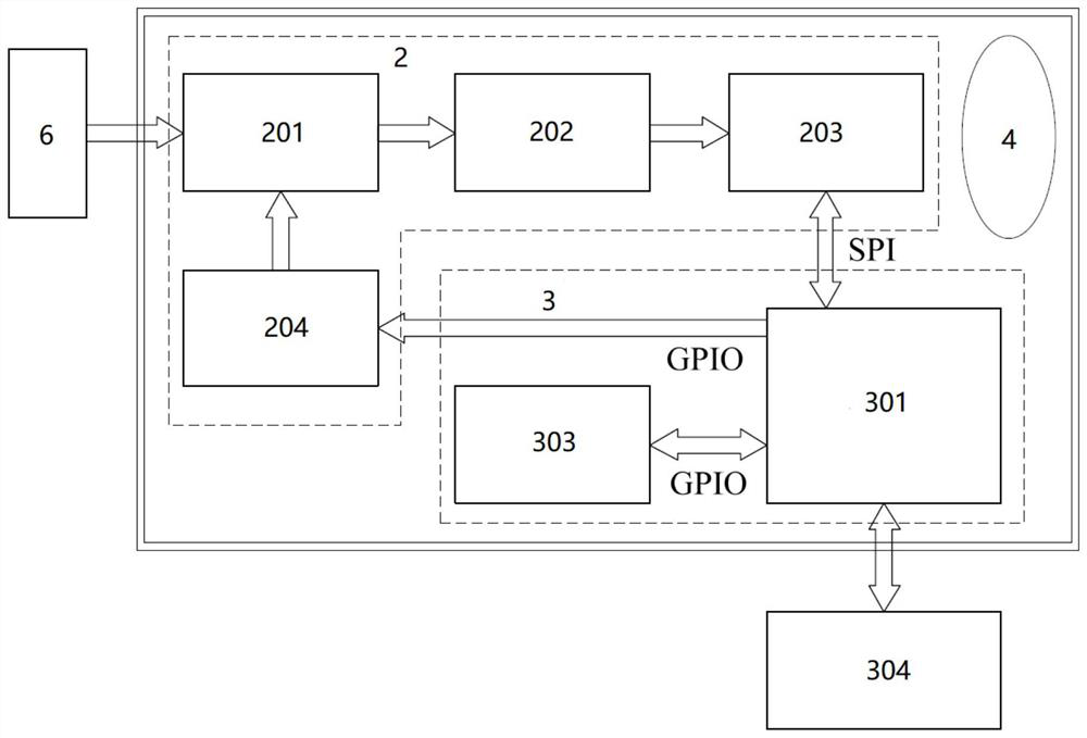
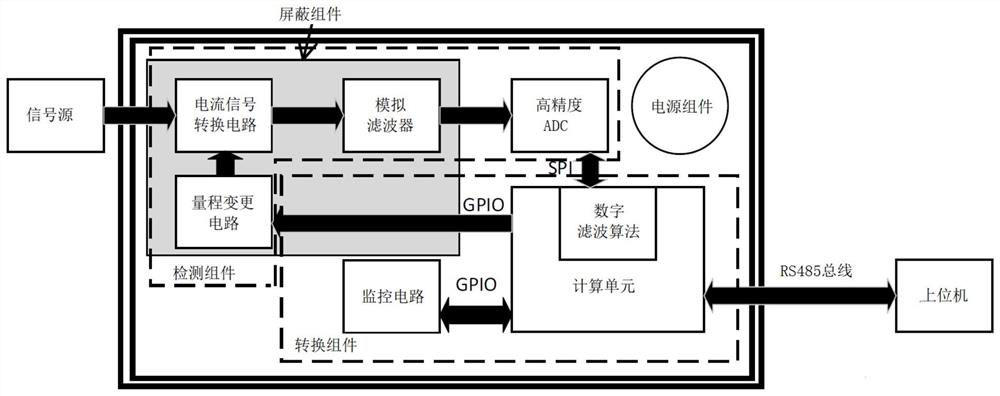
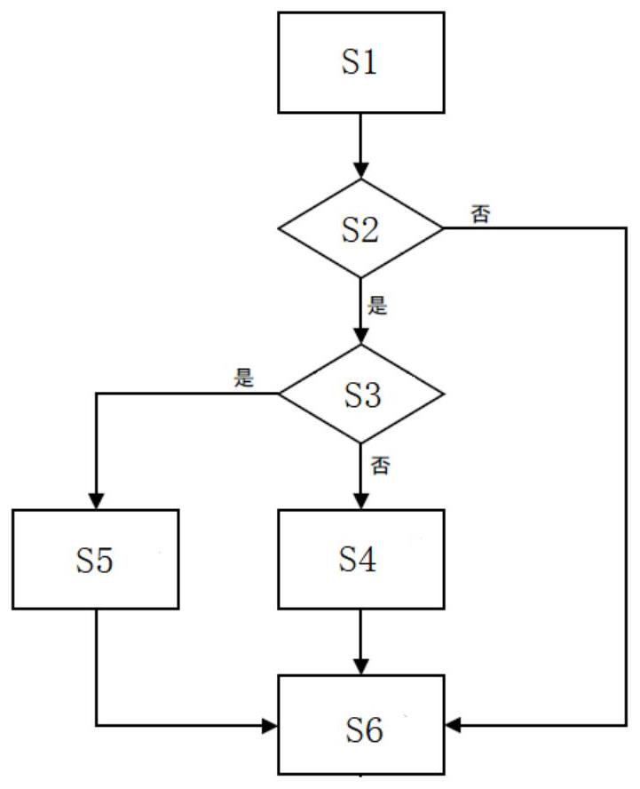
[0050] The present application relates to a weak current measurement device, including: a detection component, a conversion component, and a power supply component. The component includes a current signal conversion circuit, a filter circuit, an analog-to-digital conversion circuit and a range change circuit, and the calibration component is configured to: perform manual calibration or automatic calibration based on the current source condition of the device to be detected, wherein the Automatic calibration includes: adjusting to each detection gear and performing several detections respectively, and taking the detection average value as the correction standard for the detection data of each component. figure 1 A circuit block diagram of an exemplary embodiment of a weak current measuring device is shown. The weak current measuring device of the present invention is designed based on the principle of the high-resistance method, and a calibration component is designed as the pr...

Embodiment approach

[0060] According to a preferred embodiment, the current signal conversion circuit includes an electrometer-level operational amplifier; the input terminal of the electrometer-level operational amplifier is used to receive the current signal to be measured, and the output terminal is connected to the filter circuit, wherein , the current signal conversion circuit is provided with a first resistor at the input end of the current signal to be measured based on the principle of the high-impedance method, and a second resistor is provided at the output end of the electrometer-level operational amplifier, the first resistor and the second resistor The resistor is used to convert the current signal to be measured into a voltage signal, and is used to improve the current detection response speed in a manner of stabilizing the current signal to be measured. Specifically, the first resistor is set at the RES+ position of the circuit, and the second resistor is set at the RES- position of...


PUM


Abstract

The invention relates to a weak current measuring device, which comprises a detection assembly, a conversion assembly, a power supply assembly and a calibration assembly, and is characterized in that the calibration assembly is used for correcting detection data of each assembly and is configured to select manual calibration or automatic calibration based on a current source condition of a current device to be detected. The automatic calibration comprises the following steps: adjusting to each detection gear, respectively carrying out detection for a plurality of times, and taking a detection mean value as a correction standard of detection data of each component. The weak current measuring device is designed based on the principle of a high-resistance method, the calibration assembly is designed to serve as a front assembly of the device, it is guaranteed that the device has the high speed when detecting weak current, meanwhile, the measuring range changing circuit is integrated between the calculation unit and the current signal conversion circuit, and the measuring precision is improved. A user can adjust the current to be measured to a proper measuring range according to the approximate range of the current to be measured, the measurement accuracy is ensured, the device has high performance and practicability at the same time, and a foundation is laid for practical application of radiopharmaceutical activity field measurement.

Description

technical field [0001] The invention relates to the technical field of extremely weak current detection, in particular to a weak current measuring device. Background technique [0002] Generally, currents below the nA level are defined as weak currents. In scientific research in many fields such as nuclear technology applications, ionizing radiation, electrochemistry, and materials science, it is often necessary to carry out detection of weak currents. Especially in nuclear medicine, as more and more short-lived or ultra-short-lived artificial nuclides are used in clinical diagnosis and treatment, these nuclides decay at a high speed over time. This characteristic is the absolute measurement of activity and needs to be carried out at any time. The results of the verification work caused great difficulties. [0003] At present, the China National Institute of Metrology (NIM) has developed a 4πγ high-voltage ionization chamber activity measurement system for rapid measurement...

Claims


Application Information

Patent Timeline
IPC IPC(8): G01R19/25
Inventor 侯胜利曾卫华梁珺成杨志杰杨豪
Owner CHINA UNIV OF GEOSCIENCES (BEIJING)
Why Eureka
Try Eureka