
Energy-saving industrial energy station utilizing waste heat recovery and clean energy and operation control method

A technology of clean energy and waste heat recovery, applied in the energy industry, heating methods, household heating, etc., can solve problems such as insufficient power supply, high power consumption, waste of resources, etc., to reduce energy use costs, reduce production and operation costs, The effect of reducing power consumption

Pending Publication Date: 2022-04-12
HENAN 3 ZHANG ENERGY INVESTMENT
View PDF9 Cites 1 Cited by
  • Summary
  • Abstract
  • Description
  • Claims
  • Application Information

AI Technical Summary

Problems solved by technology

[0003] The central air-conditioning cold and heat source systems in most industrial parks in China are still extensive. In summer, air-conditioning is used for cooling, or a refrigeration room is used for cooling. The construction unit needs to purchase the main equipment of the refrigeration room according to the preliminary design of the design institute, and then install it by electromechanical The company installs mechanical and electrical projects on site, which consumes a lot of electricity, resulting in insufficient power supply; in winter, the heating system is centrally supplied by municipal heating companies, and municipal heating mainly uses coal burning, causing serious air pollution
The sewage generated in the industrial park is directly discharged, causing a waste of resources
Now in summer and winter peak electricity consumption is usually alleviated by partial power reduction, which brings great inconvenience to people's life

Method used


Image

  • Energy-saving industrial energy station utilizing waste heat recovery and clean energy and operation control method
  • Energy-saving industrial energy station utilizing waste heat recovery and clean energy and operation control method

Examples


Embodiment 1

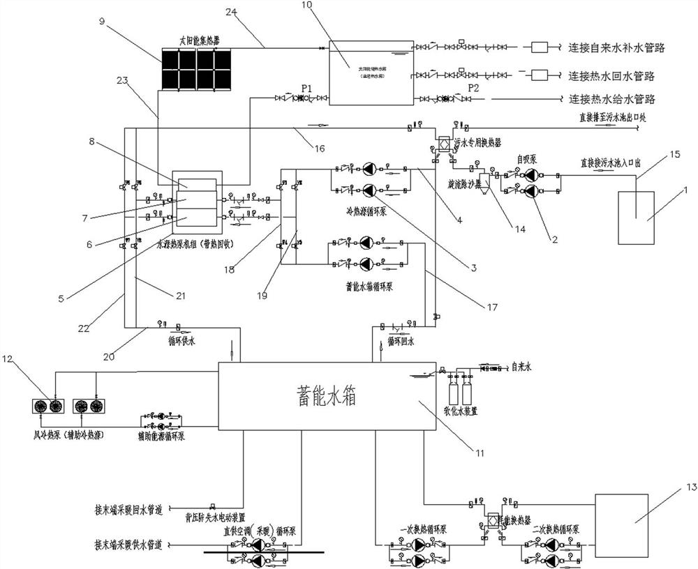
[0037] Such as figure 1 As shown, an energy-saving industrial energy station using waste heat recovery and clean energy, including sewage source heat pump system, auxiliary system, energy storage system and solar auxiliary heating system.

[0038] The sewage source heat pump system includes a sewage heat exchanger and a sewage pool 1. The sewage pool 1 is connected to the water inlet end of the sewage heat exchanger through a sewage pipe 15 equipped with a self-priming pump 2. The sewage pipe 15 is provided with a swirling sand removal Device 14. The outlet of the sewage heat exchanger is connected to the outlet of the sewage tank 1, and the refrigerant inlet and outlet of the sewage heat exchanger are respectively connected to the liquid inlet pipe 16 and the liquid return pipe 4 equipped with the cold and heat source circulation pump 3. A shunt pipe I21 and a shunt pipe II22 are connected in parallel on the liquid pipe 16, and a return pipe I18 and a return pipe II19 are co...

Embodiment 2

[0050] An operation control method of an energy-saving industrial energy station utilizing waste heat recovery and clean energy, including a summer operation method and a winter operation method;

[0051] Summer run method, including the following steps:

[0052] (1) Turn on the sewage source heat pump system for refrigeration, and start the energy storage system for energy storage:

[0053] ① Open the electric valve V1 and the electric valve V5, and the refrigerant entering the condenser 7 performs heat exchange with the sewage in the sewage tank 1 through the heat exchanger Ⅰ, so that the temperature of the refrigerant is lowered;

[0054] ② Open the electric valve V3 and the electric valve V7, the tap water entering the energy storage water tank is cooled by the evaporator 6 and then returns to the energy storage water tank, and the energy storage water tank stores energy as a cold source;

[0055] (2) Auxiliary system refrigeration: the air-cooled heat pump unit 12 is tur...

Embodiment 3

[0060] An operation control method of an energy-saving industrial energy station using waste heat recovery and clean energy. The winter operation method is as follows: in winter, the heat load of the air conditioner is low, but the heating load is large, and the sewage source heat pump system and the solar auxiliary heating system are turned on during the day for heating. and production water heating, and turn on the auxiliary system and energy storage system for heating at night.

[0061] The specific winter operation method includes the following steps:

[0062] (1) Turn on the sewage source heat pump system for heating, and at the same time start the energy storage system for energy storage:

[0063] ① Open the electric valve V2 and the electric valve V6, and the refrigerant entering the evaporator 6 exchanges heat with the sewage in the sewage tank 1 through the heat exchanger Ⅰ, so that the temperature of the refrigerant rises;

[0064] ②Open the electric valve V4 and th...


PUM


Abstract

The invention discloses an energy-saving industrial energy station utilizing waste heat recovery and clean energy. The energy-saving industrial energy station comprises a sewage source heat pump system, an auxiliary system, an energy storage system and a solar auxiliary heating system. The invention further discloses an operation control method of the energy-saving industrial energy station. The energy storage water tank is used for providing energy (cold energy is provided in summer and heat energy is provided in winter) for an air conditioner user, on one hand, the influence of load fluctuation of the air conditioner user on heat pump units (a sewage source heat pump unit and an air cooling source heat pump unit) can be reduced, and the heat pump units are always in an efficient working interval; and on the other hand, the heat pump unit can utilize off-peak electricity to refrigerate or heat and store the off-peak electricity in the energy storage water tank, so that the electricity utilization cost is reduced.

Description

technical field [0001] The invention relates to the technical field of comprehensive energy utilization, in particular to an energy-saving industrial energy station utilizing waste heat recovery and clean energy and an operation control method. Background technique [0002] At present, the construction of industrial energy stations is an important part of the country's promotion of energy production and consumption revolution. The state has provided policy support for the development of an integrated energy system with multi-subject linkages, encouraged the coordinated transformation of various energy forms such as electricity, heat, and gas, and clarified the importance of building an integrated energy network infrastructure. However, central air-conditioning is still used in industrial parks system-based. [0003] The central air-conditioning cold and heat source systems in most industrial parks in China are still extensive. In summer, air-conditioning is used for cooling...

Claims


Application Information

Patent Timeline
Patent Type & Authority Applications(China)
IPC IPC(8): F24D3/02F24D3/08F24D3/10F24D3/18F24S20/40F24F5/00F25B30/02F25B49/02
CPCY02E10/40Y02P80/10Y02P80/20
Inventor 张红晓李勇张业强原佩霞张纪张晓平
Owner HENAN 3 ZHANG ENERGY INVESTMENT
Learn More