
Temperature difference power generation control method and control device based on building outer wall

A thermoelectric power generation, building exterior wall technology, applied in circuit devices, battery circuit devices, generators/motors, etc., can solve problems such as low power generation efficiency and uneven power generation, and achieve improved power generation Guaranteed uniformity and consistent results

Active Publication Date: 2022-04-12
CHANGAN UNIV
View PDF7 Cites 0 Cited by
  • Summary
  • Abstract
  • Description
  • Claims
  • Application Information

AI Technical Summary

Problems solved by technology

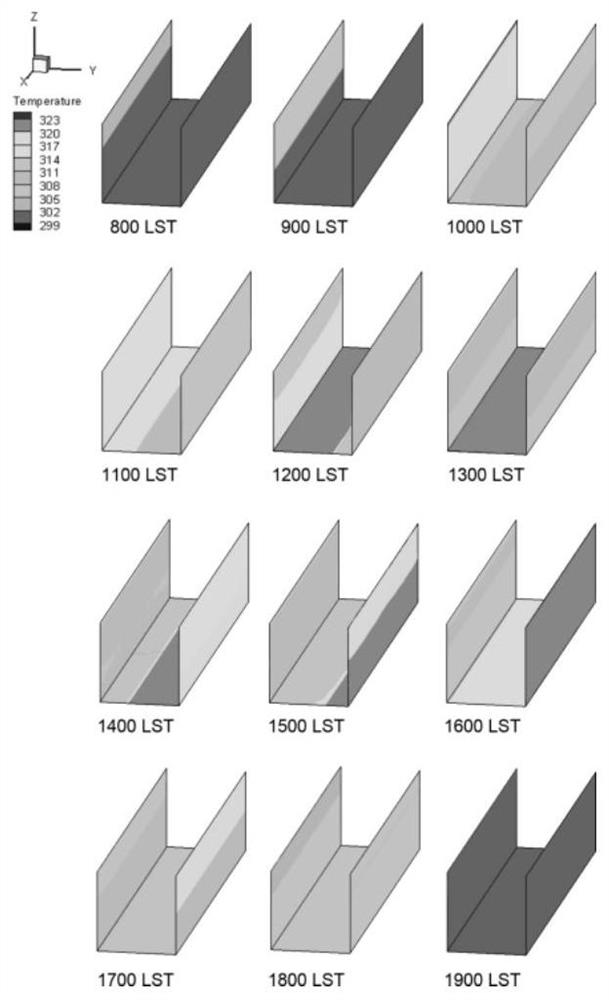
[0004] In view of the above analysis, the embodiment of the present invention aims to provide a thermoelectric power generation control method and control device based on building exterior walls to solve the problems of uneven power generation and low power generation efficiency existing in thermoelectric power generation in the prior art

Method used


Image

  • Temperature difference power generation control method and control device based on building outer wall
  • Temperature difference power generation control method and control device based on building outer wall
  • Temperature difference power generation control method and control device based on building outer wall

Examples


Embodiment 1

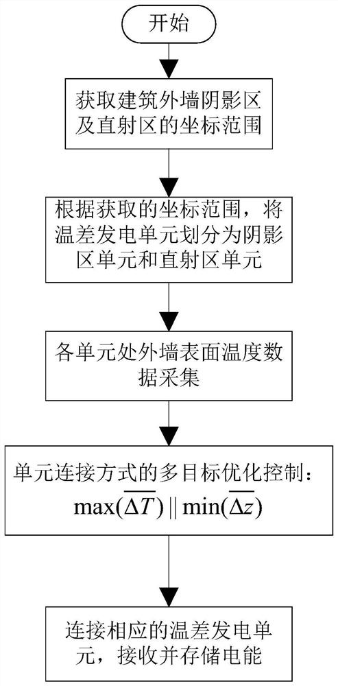
[0041] A specific embodiment of the present invention discloses a method for controlling power generation based on temperature difference of building exterior walls, the process of the method is as follows image 3 shown. combine image 3 , the method includes the following steps:

[0042] S1. Obtain the coordinate range of the shadow area and the direct area of ​​the building's outer wall at the current moment;

[0043] Specifically, Ecotect can be used to numerically simulate the insolation situation; in Ecotect, a building model is established based on the building structure, and the longitude, latitude, and current time data are input to numerically simulate the insolation situation of the building at that moment to obtain the corresponding Solar radiation data on building exterior surfaces. The horizontal line where the surface level of the building’s exterior wall is 0 is the baseline of the building’s exterior wall, with the intersection point of the baseline and the...

Embodiment 2

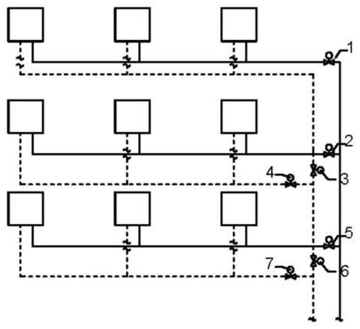
[0062] Another specific embodiment of the present invention provides a thermoelectric power generation control device based on building exterior walls, such as Figure 4 As shown, the device includes: several temperature difference power generation units arranged on the surface of the building exterior wall, a solar simulation computer 1, a temperature sensor 2, a main control chip 3, an electric storage device 4, and a thyristor relay 5;

[0063] The sunlight simulation computer 1 is used to obtain the coordinate range of the shadow area of ​​the building exterior wall and the direct radiation area, and sends the coordinate range to the main control chip;

[0064] Specifically, the insolation simulation computer 1 can use Ecotect to numerically simulate the insolation situation; in Ecotect, a building model is established according to the building structure, and the longitude, latitude, and current moment data are input to numerically calculate the insolation situation of the ...


PUM


Abstract

The invention relates to a building outer wall thermoelectric power generation control method and device based on solar radiation daily variation, belongs to the field of building new energy and energy conservation, and solves the problems that in the prior art, a building outer envelope structure thermoelectric power generation technology purely utilizes indoor and outdoor temperature difference, the power generation efficiency is low, and the power generation amount is uneven. According to the application, a plurality of thermoelectric power generation units are arranged on the building outer wall, and through hourly solar radiation analysis of the building outer wall, the maximum average temperature difference between the thermoelectric power generation units in a shadow area and a direct radiation area of the building outer wall and the minimum lead length are taken as control targets; and the building outer wall shadow area thermoelectric power generation unit and the direct incidence area thermoelectric power generation unit are connected in series to form an optimized thermoelectric power generation unit group. Through the power generation control method and device, the building outer wall temperature difference power generation efficiency and the hourly stability of the power generation amount can be remarkably improved, the method and device can be widely applied to the building new energy field such as building outer wall power generation, and support is provided for urban distributed energy system design.

Description

technical field [0001] The present invention relates to the technical field of building new energy and energy saving, in particular to a method and device for controlling power generation based on temperature difference of building exterior walls. Background technique [0002] The basic principle of thermoelectric power generation technology is the Seebeck effect of thermoelectric materials, that is, when two metal conductors or semiconductors with different free electron densities or carrier densities in different temperature environments contact each other, the electrons on the contact surface change from high to low. The concentration diffuses to the lower concentration, and the diffusion rate of electrons is proportional to the temperature difference borrowed. When there is a constant temperature difference between two conductors or semiconductors, electrons continue to diffuse and a stable voltage will be formed between the two terminals. The formula for calculating th...

Claims


Application Information

Patent Timeline
IPC IPC(8): H02N11/00H02J7/32G06Q10/04G06Q50/06
Inventor 檀姊静江超柳天祥
Owner CHANGAN UNIV
Learn More