Supercharge Your Innovation With Domain-Expert AI Agents!

Gray cast iron piston head ring groove laser cladding repair process

A technology of laser cladding and piston head, applied in metal material coating process, coating and other directions, can solve the problems of irreparable piston head, easy wear of piston ring groove, large impact force of piston ring, etc., to ensure consistent product quality Performance and stability, reliable production quality, and increased service life

Pending Publication Date: 2022-04-19
江苏智远激光装备科技有限公司
View PDF6 Cites 1 Cited by
  • Summary
  • Abstract
  • Description
  • Claims
  • Application Information

AI Technical Summary

Problems solved by technology

The main reason is that the pressure of the gas makes the unit pressure of the piston ring against the ring groove. At the same time, due to the high-speed motion of the piston, the impact force of the piston ring on the ring groove is very large; in addition, the temperature of the combustion gas is very high, so that The working temperature of the piston head is high, which leads to easy wear of the piston ring groove
The cross-section of the worn ring groove is trapezoidal, wide on the outside and narrow on the inside, and the side clearance increases, resulting in cylinder air leakage, oil blow-by, engine power performance decline, lubrication deterioration, and a large amount of carbon deposits in the combustion chamber.
Therefore, it is very necessary to strengthen and repair the piston ring groove. Most of the traditional repair methods are plasma repair, such as a plasma arc cladding repair method for continuous casting rollers provided by document number CN 102912276 A, but because the material of the piston head is Gray cast iron, at the same time, the ring groove is too narrow (6-12mm), plasma repair needs preheating and heat preservation, and many piston heads cannot be repaired

Method used


Image

  • Gray cast iron piston head ring groove laser cladding repair process
  • Gray cast iron piston head ring groove laser cladding repair process
  • Gray cast iron piston head ring groove laser cladding repair process

Examples


Embodiment 1

[0025] Taking the laser cladding repair of the piston head of a marine oil extraction machine as an example, a specific implementation method of the laser cladding repair process for the ring groove of the gray cast iron piston head is described. The specific requirements are: no pores, no cracks, hardness > 52HRC, cladding layer thickness > 0.8mm, piston ring groove width 7mm, depth 10mm, the specific steps are:

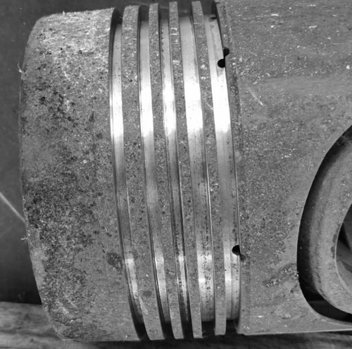
[0026] Step 1: Machining the inner facade of the damaged piston head ring groove that needs to be repaired, turning to remove the fatigue layer and oxide layer, and turning off 0.3mm on both sides of the facade, such as figure 1 shown;

[0027] Step 2: Clean the inner surface of the ring groove, remove burrs and oil stains;

[0028] Step 3: Set the process parameters of the laser cladding equipment to laser clad the iron-based alloy powder on the repaired part of the piston ring groove. During the cladding process, the piston head continues to rotate at a variable ...

Embodiment 2

[0035] The difference between embodiment 2 and embodiment 1 is that in the repair process, the parameters in step 3 are different, specifically:

[0036] The laser cladding uses a 4kW semiconductor laser as the light source, a six-axis robot and a two-axis positioner as the laser cladding motion system, an airborne powder feeder as the powder feeding mechanism, and a three-way coaxial powder feeding cladding head as the The laser head, as a whole, constitutes a laser cladding system for continuous scanning of laser cladding. The process parameters of the laser cladding are as follows: the size of the laser focus spot is φ1.8mm, and the powder feeding nozzle of the cladding head is three-way coaxial feeding. The powder nozzle has a working distance of 35mm, an inclination angle of 45°, and an output power of 1600W. The piston head is continuously rotated by the positioner to ensure a uniform cladding line speed of 11mm / s. The cladding layer is overlapped from the inside to the o...

Embodiment 3

[0038] The difference between embodiment 3 and embodiments 1 and 2 is that in the repair process, the parameters in step 3 are different, specifically:

[0039]The laser cladding uses a 4kW semiconductor laser as the light source, a six-axis robot and a two-axis positioner as the laser cladding motion system, an airborne powder feeder as the powder feeding mechanism, and a three-way coaxial powder feeding cladding head as the The laser head, as a whole, constitutes a laser cladding system for continuous scanning of laser cladding. The process parameters of the laser cladding are as follows: the size of the laser focus spot is φ1.8mm, and the powder feeding nozzle of the cladding head is three-way coaxial feeding. The powder nozzle has a working distance of 35mm, an inclination angle of 60°, and an output power of 2000W. The piston head is continuously rotated by the positioner to ensure a uniform cladding line speed of 12mm / s. The cladding layer is overlapped from the inside to...


PUM

PropertyMeasurementUnit
Thicknessaaaaaaaaaa
Hardnessaaaaaaaaaa

Abstract

The invention relates to a laser cladding repair process for a gray cast iron piston head ring groove. Comprising the following steps: (1) machining an inner vertical surface, needing to be repaired, of a damaged piston head ring groove; (2) the inner vertical face of the annular groove is cleaned; (3) setting process parameters through laser cladding equipment to carry out laser cladding of iron-based alloy powder on the repaired part of the piston ring groove; (4) when the opposite face of the ring groove is repaired, the power is reduced by 5-10%, and other parameters are consistent with the parameters of the first vertical face; (5) the laser cladding process of other ring grooves of the piston head is completed in sequence; and (6) after laser cladding is completed and the piston head is naturally cooled, dye penetrant inspection is conducted, the problem that cracks and air holes are prone to being generated in laser cladding of the inner vertical face of the annular groove of the gray cast iron piston head under the condition that preheating and heat preservation are not conducted is solved, laser cladding repairing and strengthening of the inner vertical face of the annular groove of the gray cast iron piston head are achieved, and a new piston head can be replaced; and the service life of the piston head is greatly prolonged, and remanufacturing and reutilization of the old piston head are achieved.

Description

technical field [0001] The invention relates to the field of piston remanufacturing, in particular to a laser cladding repair process for gray cast iron piston head ring grooves, which is suitable for the repair and manufacture of gray cast iron, ductile iron and other cast iron piston ring grooves. Background technique [0002] One of the main parts of the piston engine of the engine, it forms the piston group with piston rings, piston pins and other parts, and forms the combustion chamber together with the cylinder head. [0003] The most common damage to the piston is the wear of the piston ring groove, the wear of the piston skirt, the wear of the piston pin and the wear of the piston pin seat hole, etc. The piston ring groove is the largest wear part of the piston, especially the first piston ring groove is the most severely worn. The main reason is that the pressure of the gas makes the unit pressure of the piston ring on the ring groove. At the same time, because the...

Claims


Application Information

Patent Timeline
IPC IPC(8): C23C24/10C22C37/10C22C37/08B22F7/06B22F1/00
CPCC23C24/106C22C37/10C22C37/08B22F7/062B22F2007/068
Inventor 林学春农光壹林培晨谭长伟杭骏祥
Owner 江苏智远激光装备科技有限公司
Features
  • R&D
  • Intellectual Property
  • Life Sciences
  • Materials
  • Tech Scout
  • Unparalleled Data Quality
  • Higher Quality Content
  • 60% Fewer Hallucinations
Learn More