Gas circuit switching device of expectoration machine and expectoration system

A technology for switching devices and coughing up sputum, which is applied in the field of medical devices, and can solve the problems of increasing the design and manufacturing difficulty of the expectoration machine, complex internal air circuit structure, and high manufacturing cost of the expectoration machine, so as to achieve good working performance and a neat and simple overall structure , The overall structure is simple and efficient

Active Publication Date: 2022-04-26
河北金康安医疗器械科技有限公司
View PDF8 Cites 0 Cited by
  • Summary
  • Abstract
  • Description
  • Claims
  • Application Information

AI Technical Summary

Problems solved by technology

In order to realize the switching of the internal gas circuit, most of the existing expectoration machines have designed a complex gas circuit switching structure and control system, resulting in high manufacturing costs and complicated manufacturing processes of the expectoration machine; and increased medical costs.
[0007] At the same time, due to the complex structure of the internal air circuit, the flow path of the air flow becomes longer, which is prone to the problem of large flow loss; in addition, in order to produce the high-frequency oscillation effect of the respiratory air flow, it is necessary to increase the air flow switching structure based on the existing complexity. High-frequency oscillation device, which further increases the design and manufacturing difficulty of the expectoration machine

Method used


Image

  • Gas circuit switching device of expectoration machine and expectoration system
  • Gas circuit switching device of expectoration machine and expectoration system
  • Gas circuit switching device of expectoration machine and expectoration system

Examples


Embodiment 1

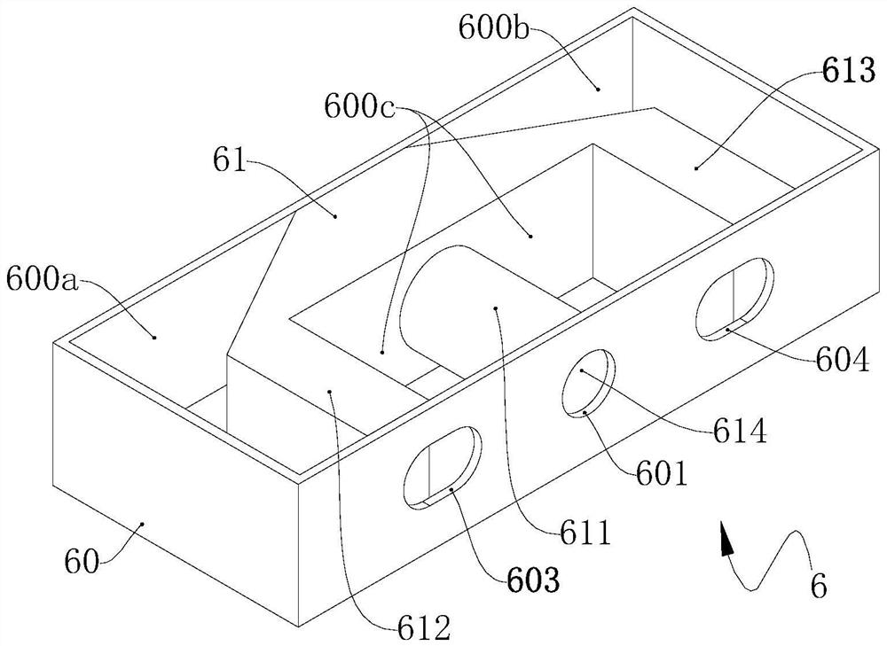
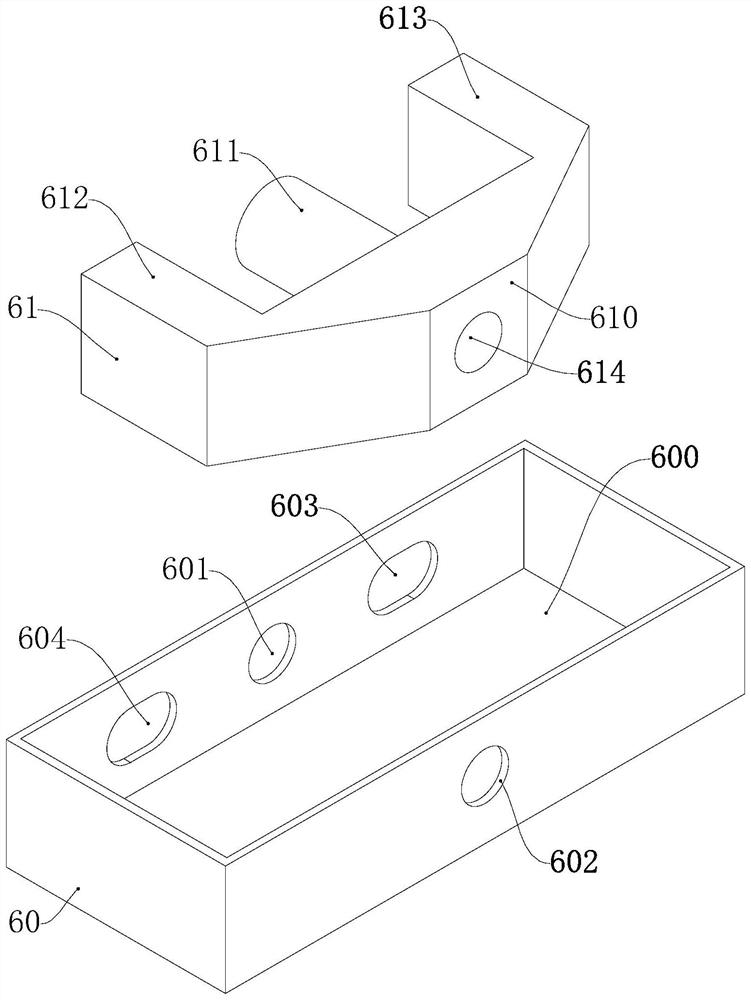
[0053] This embodiment relates to an air circuit switching device for an expectorant machine, which has a relatively simple structure and is easy to construct, and is conducive to reducing the manufacturing cost of the expectorant machine 7. An exemplary structure of which is figure 1 and shown in Figure 2.

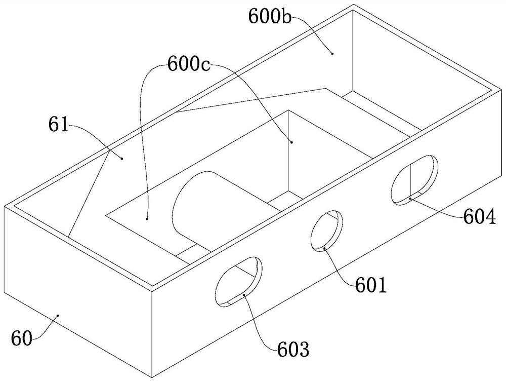
[0054] In general, the air circuit switching device of the expectoration machine is set in the expectorator 7 and connected between the fan 10 of the expectorator 7 and the patient's respiratory organ 30 . The air circuit switching device 6 includes a housing 60 and a valve core 61; wherein, a chamber 600 is formed in the housing 60, and the valve core 61 is movably arranged in the chamber 600, and can be driven by an external force to open the first valve position, second valve position and third valve position.

[0055] The housing 60 is provided with an air inlet 601 for communicating with the outlet of the fan 10, an exhaust port 602 for communicating with the inlet...

Embodiment 2

[0069] This embodiment also relates to an air circuit switching device for an expectoration machine. The air circuit switching device 6 of this embodiment is designed in accordance with the general principle of the present invention, and also includes two parts: a housing 60 and a valve core 61; an exemplary structured as Figure 5 and Figure 6 shown.

[0070] Specifically, the housing 60 of this embodiment is in the shape of a cylinder, and the valve core 61 rotates around the axis of the housing 60 and moves in the chamber 600 . The air inlet 601, the patient communication port 603 and the external communication port 604 are arranged at intervals on the side wall of the housing 60, and the exhaust port 602 is opened at the bottom of the housing 60. The cylindrical housing 60 is adopted, and the switching between different valve positions is realized by the rotating and moving valve core 61, which also has the characteristics of regular and simple structure and is convenient...

Embodiment 3

[0077] This embodiment relates to a sputum expectoration system, and an exemplary system configuration thereof is as follows: Figure 9 Shown; This expectoration system mainly comprises expectoration machine 7, cooling system 25, power supply unit 26 etc. Wherein, the blower unit 1 and the microcomputer processing unit 2 are the main components of the sputum expectoration machine 7.

[0078] In this embodiment, the sputum expectoration machine 7 is provided with a blower unit 1 and a microcomputer processing unit 2 for controlling the blower unit 1 to switch between the stop mode, the inhalation mode and the exhalation mode of the sputum expectoration machine 7. At the same time, the blower unit 1 is provided with a blower fan 10, and the air circuit switching device of the expectoration machine provided in the first or second embodiment; the first valve position, the second valve position and the third valve position of the valve core 61 They respectively correspond to the a...


PUM


Abstract

The invention provides an air path switching device of an expectoration machine and an expectoration system. The air path switching device of the expectoration machine comprises a shell and a valve element, a cavity is formed in the shell, and the valve element is movably arranged in the cavity and can be driven by external force to be switched among a first valve position, a second valve position and a third valve position. Wherein the shell is provided with an air inlet, an air outlet, a patient communication port and an external communication port; the valve element comprises a body, partition plates and an exhaust port communicating hole, wherein the partition plates and the exhaust port communicating hole are arranged on the body. The partition plates divide the cavity into a plurality of branch cavities. Under different valve positions, different communicating ports can be communicated through the exhaust port communicating hole or the branch cavity, so that the purpose of switching air paths of the expectoration machine under different modes is achieved. According to the gas path switching device of the expectoration machine, the branch cavities serve as communicating channels between the different communicating openings, the smoothness of gas flowing is guaranteed, and the gas buffering effect is achieved; the whole air path switching device is simple and efficient in structure, and the manufacturing cost of the expectoration machine can be reduced.

Description

technical field [0001] The invention relates to the technical field of medical devices, in particular to an air circuit switching device for an expectoration machine. In addition, the present invention also relates to a expectoration system. Background technique [0002] Coughing is one of the important defense mechanisms of the human body. It prevents poisonous gas, bacteria and other harmful substances or various foreign substances from entering the airway; it keeps the airway unobstructed by discharging inhaled foreign substances or airway secretions out of the airway. [0003] For healthy people, breathing and coughing are the basic functions; for some critically ill patients, when their respiratory system is impaired, basic breathing functions and coughing are difficult to complete independently. For example, in patients with radiculopathy or restrictive lung disease with symptoms of respiratory muscle paralysis and low cough function, foreign substances may cause pneu...

Claims


Application Information

Patent Timeline
Patent Type & Authority Applications(China)
IPC IPC(8): A61M16/00A61M39/10A61M39/02
CPCA61M16/0006A61M39/10A61M39/02
Inventor 李罗臣曹学岩殷腾超刘康康许丽霄
Owner 河北金康安医疗器械科技有限公司
Why Eureka
Try Eureka