
EUV radiation source generating device for photoetching machine

A technology for generating devices and radiation sources, applied in the field of EUV radiation source generating devices, can solve the problems of increasing the intensity of EUV radiation sources, only one group, and low EUV radiation intensity

Pending Publication Date: 2022-04-26
张玥
View PDF2 Cites 0 Cited by
  • Summary
  • Abstract
  • Description
  • Claims
  • Application Information

AI Technical Summary

Problems solved by technology

This patent can prepare EUV radiation sources, but due to the small number of fuel droplets carried at a time, the intensity of the EUV radiation generated is not high. If you choose to increase the volume of fuel droplets to increase the amount of fuel carried in a single time, the radiation intensity of the laser beam will also decrease. Corresponding needs increase, but the laser intensity excited by the current laser does not meet the requirements, so it cannot be used as a radiation source for EUV lithography machines at present
[0007] In the case of the limited laser intensity excited by the existing laser, the current existing technology is to continuously hit 50,000 tin droplets with a diameter of about 20 microns per second to realize the preparation of the EUV radiation source, but its performance is still There is room for further improvement. Since it is unavoidable for multiple groups of lasers to hit the same metal tin droplet, the number of lasers can only be one group. If multiple groups of lasers can be prevented from hitting the same metal tin droplet, the number of lasers can be increased, thereby increasing Intensity of EUV Radiation Source

Method used


Image

  • EUV radiation source generating device for photoetching machine
  • EUV radiation source generating device for photoetching machine
  • EUV radiation source generating device for photoetching machine

Examples


Embodiment Construction

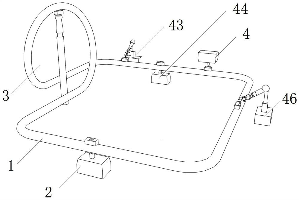
[0038] Such as Figure 1-6 As shown, it is an EUV radiation source generating device for a lithography machine according to the present invention, which includes a conveyor belt 1, which is arranged in a ring, and the belt body can move freely within the range limited by the conveyor belt frame, and runs at a constant speed driven by a servo motor Or pulse operation, the transmission belt contains multiple through holes, the belt body is coated with silicon material and molybdenum material, and has the ability to reflect extreme ultraviolet light; it also includes EUV radiation source generation unit 2, cleaning unit 3, fuel injection unit 4 and Vacuum control unit 5;

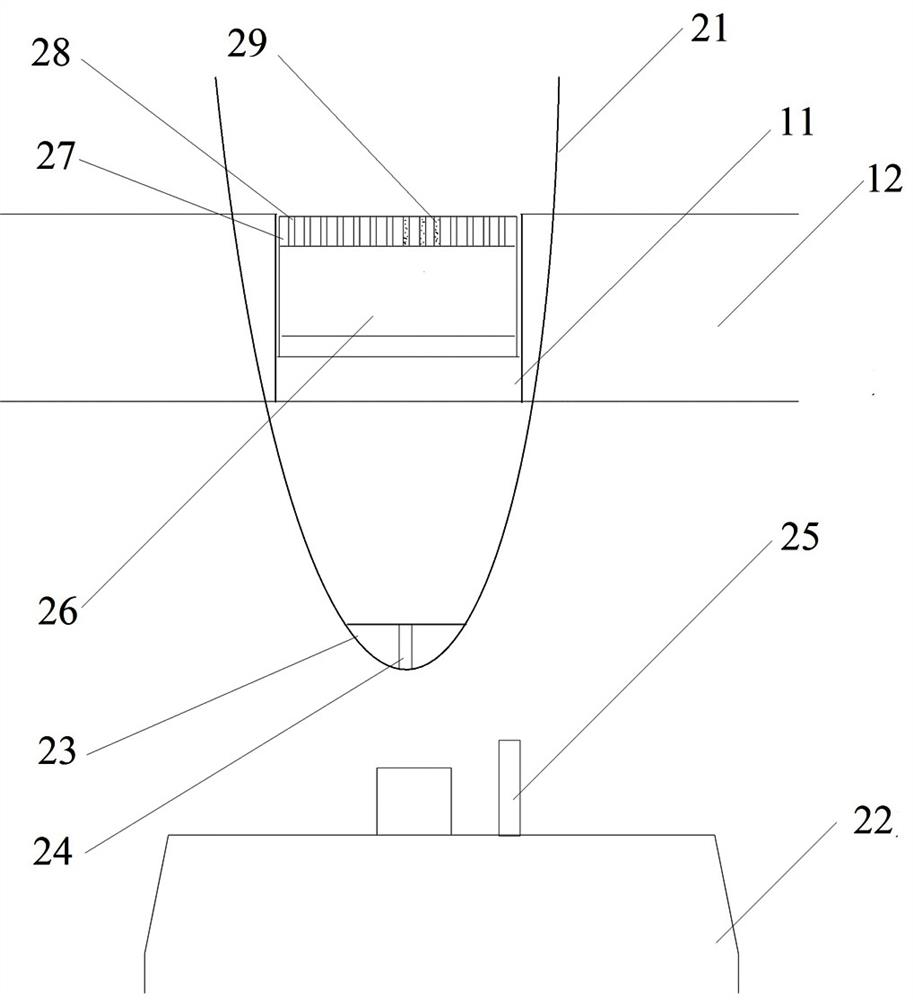
[0039] The EUV radiation source generating unit 2 includes a reflective cup 21 sleeved on a part of the conveyor belt and a laser 22 arranged below the reflective cup; the cup body of the reflective cup is provided with an opening for the conveyor belt to pass through, and the lower part of the reflective cup i...


PUM

PropertyMeasurementUnit
The inside diameter ofaaaaaaaaaa
Heightaaaaaaaaaa
Thicknessaaaaaaaaaa

Abstract

The invention discloses an EUV radiation source generating device for a photoetching machine. The EUV radiation source generating device comprises a conveying belt, the device is characterized by further comprising an EUV radiation source generation unit, a cleaning unit, a fuel injection unit and a vacuum control unit, the EUV radiation source generation unit comprises a reflection cup and a laser; a light through hole is formed in a belt body of the conveying belt, a laser crystal is arranged in the light through hole, a coating is arranged on the upper portion of the laser crystal, a plurality of micron holes are formed in the coating, and fuel capable of generating extreme ultraviolet light is arranged in the micron holes. The cleaning unit comprises a fragment cleaning cavity and a steam jet; the fuel injection unit comprises a fuel injection cavity and a high-pressure nozzle; a first mechanical arm and an auxiliary light source are arranged on the front portion of the fuel injection cavity, and a second mechanical arm is arranged on the rear portion of the fuel injection cavity. The continuous operation of the device is effectively realized, the reliability of fuel filling is ensured, the production efficiency of the device is improved, and meanwhile, the aim of improving the photoetching precision is fulfilled.

Description

technical field [0001] The invention belongs to the technical field of photolithography machine auxiliary devices, and in particular relates to an EUV radiation source generating device for a photolithography machine. Background technique [0002] Extreme Ultra-violet lithography (Extreme Ultra-violet), often called EUV lithography, is a lithography technology that uses extreme ultraviolet light with a wavelength of 10-14 nanometers as the radiation source, and the current common wavelength is 13.4nm. Among the existing lithography machines, the most advanced lithography machines have reached the 3nm level, and the design scheme of the 1nm level NA EUV lithography machine has also been completed; the difficulty in manufacturing high-end lithography machines is EUV The manufacture and collection of light, but the existing domestic lithography machines lack the manufacturing technology of EUV extreme ultraviolet light. [0003] Photoluminescence (PL for short) is a kind of co...

Claims


Application Information

Patent Timeline
IPC IPC(8): G03F7/20H05G2/00
CPCG03F7/2004H05G2/003G03F7/70033H05G2/008G03F7/70925
Inventor 张玥
Owner 张玥
Learn More