Supercharge Your Innovation With Domain-Expert AI Agents!

Nitrogen injection thermal recovery system for oil shale

A technology of oil shale and nitrogen, which is applied in the direction of exploitation fluid, earthwork drilling, wellbore/well components, etc., can solve the problems of difficult implementation, high power requirement and difficulty in on-site implementation of shale oil thermal recovery, and achieves Suitable for popularization and use, improving heating efficiency and facilitating production operations

Pending Publication Date: 2022-05-06
PETROCHINA CO LTD
View PDF0 Cites 0 Cited by
  • Summary
  • Abstract
  • Description
  • Claims
  • Application Information

AI Technical Summary

Problems solved by technology

[0004] 1. Hot steam injection heating technology requires extremely high dryness and high investment costs. Moreover, the injected steam condenses into water at the bottom of the well, which will cause damage to the formation. Severe water sensitivity will cause the formation pores to be completely blocked, and oil and gas cannot flow.
[0005] 2. Wireless radio frequency heating technology requires high power and is difficult to realize on site;
[0006] 3. Electrofrac TM technology has high investment cost, complex operation and high technical difficulty;
[0007] 4. E-ICP heating technology is difficult to control. It is necessary to build a freezing wall underground, which has high requirements on the heater and is easy to burn the heater.
[0008] Aiming at the problems of high difficulty in on-site implementation of shale oil thermal recovery in related technologies, high economic cost and low heating efficiency, no effective solution has been given so far

Method used


Image

  • Nitrogen injection thermal recovery system for oil shale
  • Nitrogen injection thermal recovery system for oil shale
  • Nitrogen injection thermal recovery system for oil shale

Examples


Embodiment Construction

[0058] In order to have a clearer understanding of the technical features, purposes and effects of the present invention, the specific implementation manners of the present invention will now be described with reference to the accompanying drawings.

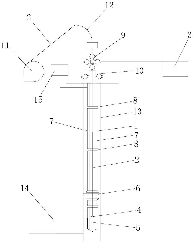
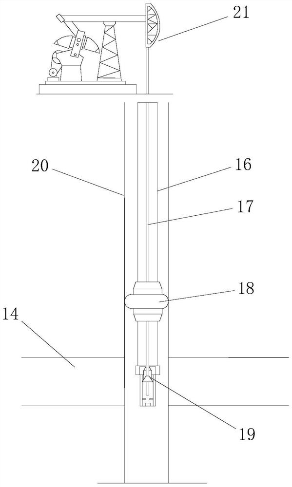
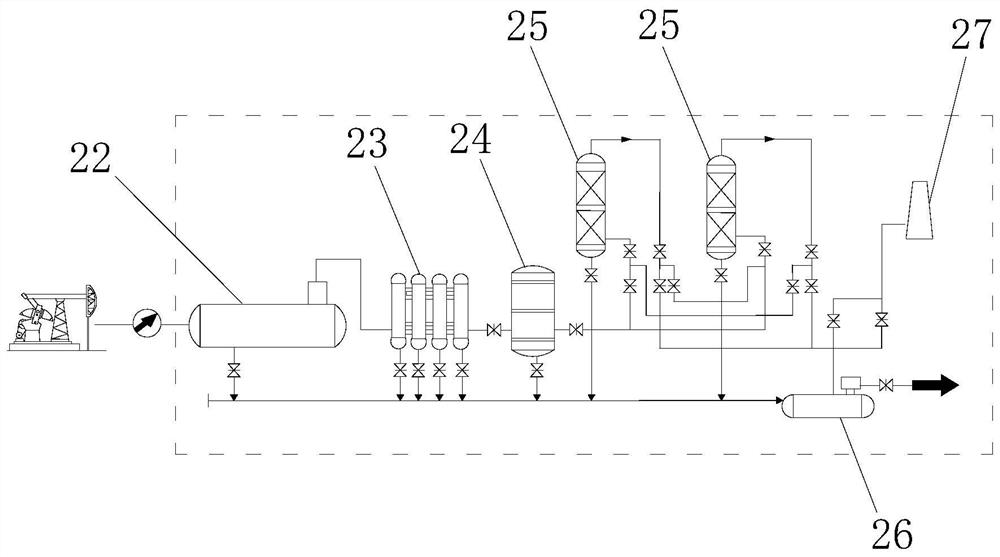
[0059] Such as Figure 1 to Figure 3 As shown, the present invention provides a nitrogen injection thermal recovery system for oil shale. The nitrogen injection thermal recovery system for oil shale includes a downhole heating device 100, a downhole oil recovery device 200 and a ground treatment device 300, wherein:

[0060] The downhole heating device 100 includes a first heat insulation pipe 1 located in the heat injection well and a nitrogen generating device 3 for delivering nitrogen gas into the heat injection well, wherein: the first heat insulation pipe 1 is vertically arranged in the heat injection well, and the first insulation The top of the heat pipe 1 is fixed at the wellhead of the heat injection well, the bottom end...


PUM


Abstract

The invention relates to an oil shale nitrogen injection thermal recovery system which comprises an underground heating device, an underground oil recovery device and a ground treatment device, the underground heating device comprises a first heat insulation pipe and a nitrogen generation device, an igniter is arranged on the first heat insulation pipe, and a nitrogen output port of the nitrogen generation device is communicated with the interior of the first heat insulation pipe; an air injection hole is formed in the bottom of the first heat-insulating pipe; the underground oil production device comprises a second heat insulation pipe, an oil well pump is arranged on the second heat insulation pipe, and the production well is communicated with the heat injection well through formation pores and cracks; the ground treatment device comprises a first-stage oil-gas separation device and a second-stage oil-gas separation device which are connected with each other, a liquid inlet of the first-stage oil-gas separation device is connected with the second heat insulation pipe, and a liquid outlet of the first-stage oil-gas separation device and a liquid outlet of the second-stage oil-gas separation device are both connected with the oil collecting pipeline. The technical problems of large implementation difficulty, high economic cost and low heating efficiency of a shale oil thermal recovery site are solved.

Description

technical field [0001] The invention relates to the technical field of shale oil development, in particular to an oil shale nitrogen injection thermal recovery system. Background technique [0002] China is very rich in oil shale resources, ranking fourth in the world in terms of resource volume and third in the world in terms of technical recoverability. Shale oil is an important alternative source of my country's oil resources and is related to domestic energy security. [0003] At this stage, the development of low- and medium-maturity oil shale in my country has not achieved a substantial breakthrough in industrialization. At present, the most effective method is heating and mining. The commonly used heating method in my country is hot steam heating technology, while the heating method in foreign countries is radio frequency Heating technology, Exxon - Mobil's Electrofrac TM technology and Shell's E-ICP heating technology. But which technology has the following problems:...

Claims


Application Information

Patent Timeline
Patent Type & Authority Applications(China)
IPC IPC(8): E21B43/16E21B43/24E21B43/34
CPCE21B43/168E21B43/24E21B43/34
Inventor 张吉昌赵永仁金兆勋程玉新王大伟吴一尘韩耀龙孙田孙贺
Owner PETROCHINA CO LTD
Features
  • R&D
  • Intellectual Property
  • Life Sciences
  • Materials
  • Tech Scout
  • Unparalleled Data Quality
  • Higher Quality Content
  • 60% Fewer Hallucinations
Learn More