
Air inlet system of aero-engine and aero-engine

A technology of aero-engine and air intake system, applied in the direction of engine components, machines/engines, fuel air intake, etc., can solve the problem of carbon deposition at the input port and fuel injection port of the mixed gas, affecting the efficiency of the combustion chamber, entering the combustion chamber, etc. problem, to achieve the effect of improving combustion efficiency, improving vibration phenomenon, and facilitating uniform distribution

Pending Publication Date: 2022-05-06
重庆佳瑞斯科技有限公司
View PDF0 Cites 0 Cited by
  • Summary
  • Abstract
  • Description
  • Claims
  • Application Information

AI Technical Summary

Problems solved by technology

[0002] In an aeroengine, the air intake system is usually divided into active control type and passive control type. The intake valve in the active control type is usually actively controlled to open and close, and the intake valve in the passive control type is usually controlled by the air pressure of the intake air. The pressure difference in the combustion chamber is self-adaptive to open and close the intake valve. In the existing passive control intake system, when the combustion pressure in the combustion chamber increases, the intake valve will be driven to close. During the closing process of the intake valve During the process, part of the exhaust gas will flow back through the valve channel, and the high-pressure exhaust gas will easily hit the fuel injection port and the mixed gas input port, which will easily cause the mixed gas input port to be filled with exhaust gas, and the exhaust gas will enter the combustion chamber for the second time with the intake air, affecting The efficiency of the combustion chamber, and it is easy to generate carbon deposits at the gas mixture input port and the fuel injection port, resulting in blockage

Method used


Image

  • Air inlet system of aero-engine and aero-engine

Examples


Embodiment Construction

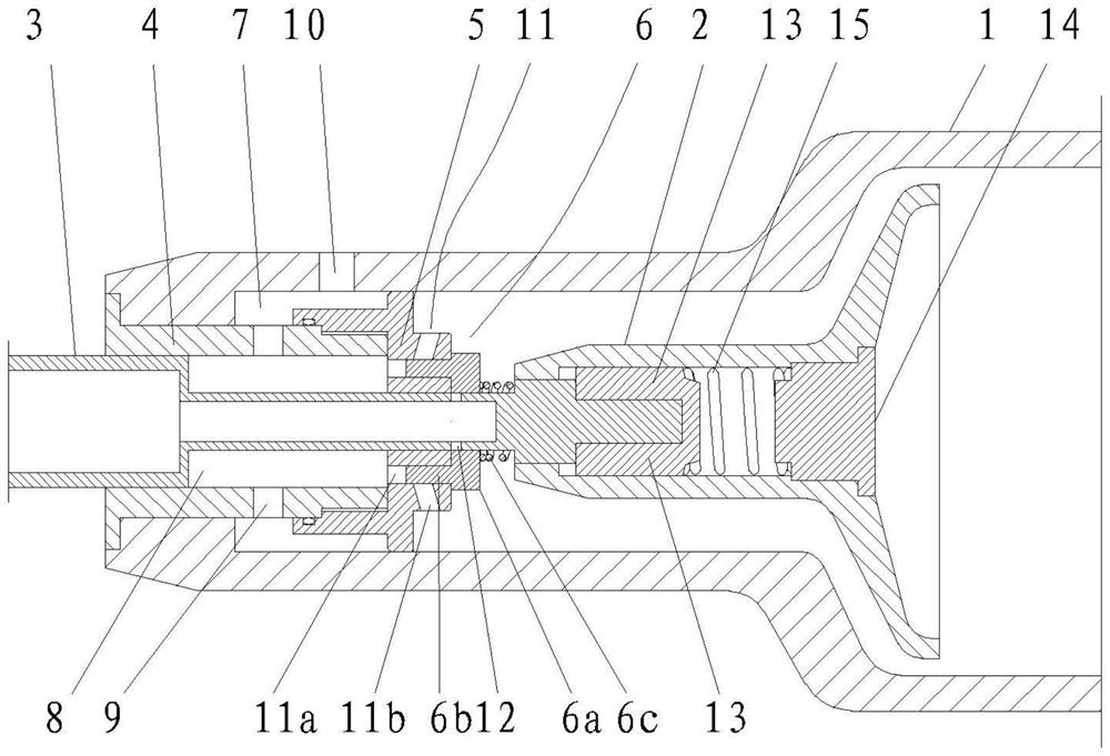
[0020] As shown in the figure, this embodiment provides a linear control device for the accelerator pedal, including an air intake seat 1 and a valve 2, and the valve 2 is installed on the right side of the air intake channel in the air intake seat 1 in an elastic sliding manner , also includes fuel injection pipe 3, mixture gas pipe sleeve 4, mixture gas nozzle 5 and opening and closing door 6;

[0021] The mixed gas pipe cover 4 is set inside the air intake seat 1, the mixed gas nozzle 5 is closed on the right end of the mixed gas pipe sleeve 4, and the outer circle of the mixed gas nozzle 5 is sealed with the inner circle of the air intake seat 1, so that the mixed gas nozzle 5 A closed annular outer air storage chamber 7 is formed between the trachea sleeve 4 and the air intake seat 1;

[0022] The fuel injection pipe 3 is set inside the mixed gas pipe sleeve 4, and a closed annular inner gas storage chamber 8 is formed between the fuel injection pipe 3 and the mixed gas p...


PUM


Abstract

The aero-engine air inlet system comprises an air inlet seat and an air valve, the air valve is installed on the right side of an air inlet channel in the air inlet seat in an elastic sliding mode, and the aero-engine air inlet system is characterized by further comprising an oil spraying pipe, a mixed air pipe sleeve, a mixed air spraying head and an opening and closing door; according to the gas inlet system, the gas inlet cavity is divided into multiple spaces, uniform distribution of mixed gas is facilitated, sufficient mixing of the mixed gas and fuel oil is guaranteed, meanwhile, the door is driven to be opened and closed through the gas pressure of the mixed gas, the response speed of the structure is high, gas spraying holes and oil spraying holes can be opened or closed in time, and the service life is prolonged. The oil injection hole and the air inlet can be rapidly opened and closed in a self-adaptive mode along with all strokes, waste gas in the combustion chamber can be effectively prevented from flowing back, the phenomenon of carbon deposition at the air inlet and the oil injection hole is avoided, and the combustion efficiency in the combustion chamber is comprehensively improved through the two aspects that fuel oil and mixed gas are evenly mixed and combined to prevent waste gas from flowing back.

Description

technical field [0001] The invention relates to the technical field of engines, in particular to an aeroengine intake system and an aeroengine. Background technique [0002] In an aeroengine, the air intake system is usually divided into active control type and passive control type. The intake valve in the active control type is usually actively controlled to open and close, and the intake valve in the passive control type is usually controlled by the air pressure of the intake air. The pressure difference in the combustion chamber is self-adaptive to open and close the intake valve. In the existing passive control intake system, when the combustion pressure in the combustion chamber increases, the intake valve will be driven to close. During the closing process of the intake valve During the process, part of the exhaust gas will flow back through the valve channel, and the high-pressure exhaust gas will easily hit the fuel injection port and the mixed gas input port, which ...

Claims


Application Information

Patent Timeline
IPC IPC(8): F02M35/10F02B77/04F01L15/18F01L15/20
CPCF02M35/10F02M35/10216F02M35/10242F02M35/10295F02B77/04F01L15/18F01L15/20
Inventor 胡艳红薛向明高志杰
Owner 重庆佳瑞斯科技有限公司
Learn More