
Fabrication method of distributed quantum sensor and sensing microstructure based on pulsed light

A pulsed light and distributed technology, which is applied in the direction of transmitting sensing components using optical devices, converting sensor output, and coupling of optical waveguides, can solve the problems of difficult quantification of measurement results, affecting sensing accuracy, and different reflection effects. Achieve the effects of improving measurement accuracy, low cost, and easy production

Active Publication Date: 2022-06-17
ANHUI GUOSHENG QUANTUM TECH CO LTD
View PDF7 Cites 6 Cited by
  • Summary
  • Abstract
  • Description
  • Claims
  • Application Information

AI Technical Summary

Problems solved by technology

The above-mentioned patent distributes and installs multiple quantum dots with different reflection wavelengths on an optical fiber. During detection, the detection results of different quantum dots can be distinguished, and then the distributed sensing function is realized. However, in this design, not only the preparation The process of various types of quantum dots is relatively cumbersome, and it is difficult to distinguish between reflected fluorescence with different wavelengths and trigger laser light. At the same time, due to the difference of each quantum dot, the reflection effect produced by the excitation light of the same wavelength is different, which leads to The measurement results of different sensing points are difficult to quantify, which ultimately affects the accuracy of sensing

Method used


Image

  • Fabrication method of distributed quantum sensor and sensing microstructure based on pulsed light
  • Fabrication method of distributed quantum sensor and sensing microstructure based on pulsed light
  • Fabrication method of distributed quantum sensor and sensing microstructure based on pulsed light

Examples


Embodiment 1

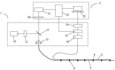
[0044] see attached figure 1 , the present embodiment is a distributed quantum sensor based on pulsed light, including a trigger source 1, a processing terminal 2 and a sensing fiber 3. The sensing fiber 3 is provided with several groups of detection areas, and each detection area is provided with There are quantum dots 6. In this embodiment, the light-emitting quantum dots are selected as diamond-containing NV color center particles with a length, width and height of 300 nm and a concentration of 2 ppm. The trigger source 1 is used to generate a special pulse light source, and couple the special pulse light source into the transmission. In the sensing fiber 3, the quantum dots 6 generate stress fluorescence under the irradiation of a special pulsed light source, and the stress fluorescence generated by the quantum dots 6 at different positions all return along the sensing fiber 3 and are uniformly received by the processing terminal 2. The processing terminal 2. Classify the ...

Embodiment 2

[0051] Considering that the data accuracy obtained by using the all-optical method to measure is not high enough as mentioned above, the all-optical method is characterized by a large detection interval, but the detection accuracy is slightly lower, this embodiment is based on optical magnetic resonance technology (ODMR), in Embodiment 1 On the basis of the microwave part, the technology can further improve the sensing accuracy;

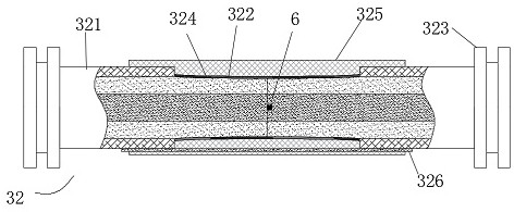
[0052] as attached Figure 5 and 6 As shown, the sensing fiber 3 is a double-wire structure composed of a microwave transmission line. The trigger source 1 also includes a microwave source. The microwave source consists of a microwave generator 14, a microwave switch 15, and a microwave amplifier 16. The microwave source is used to generate microwaves. It can be either continuous microwave or pulsed microwave. In this example, the microwave is preferably a rectangular pulsed microwave, and the rectangular pulsed microwave is compatible with a specia...

Embodiment 3

[0056] In this embodiment, based on the aforementioned technology, a simple distributed quantum optical fiber sensing model is set so as to understand how the processing terminal performs the classification of fluorescence information. Of course, this is only one of the idealized models, not a kind of this solution. limit.

[0057] see attached Figure 11 , there are four quantum dots distributed at equal intervals on the fiber, namely a, b, c and d. The pulsed light is transmitted in the fiber from left to right, and the four quantum dots are excited in turn. The distance of the detector is different, so there is a time difference in the time when the quantum dot is perceived by the photodetector. Under the stimulation of the first pulsed light, the fluorescence information of the four quantum dots recorded by the photodetector is a1, b1, c1, and d1, after a pulse interval, the second pulse light continues to stimulate the four quantum dots, and the fluorescence information ...


PUM

PropertyMeasurementUnit
sizeaaaaaaaaaa

Abstract

The invention relates to the technical field of NV color center sensing. The scheme is a distributed quantum sensor based on pulsed light, which includes a trigger source, a processing terminal and a sensing fiber. The sensing fiber is provided with several groups of detection areas, each Quantum dots are set in each detection area, the trigger source is used to generate a special pulse light source, and the special pulse light source is coupled into the sensing fiber, the quantum dots produce stress fluorescence under the irradiation of the special pulse light source, compared to In the prior art, the present invention can realize the distributed sensing of a carrier optical fiber by using the same quantum dot, which has lower cost, easier production, and easier distinction between reflected fluorescence and trigger light filtering, and because the same quantum dot is used , the present invention can use trigger light of a specific wavelength to realize efficient triggering of all quantum dots and improve measurement accuracy. At the same time, the same quantum dot is used for measurement, and the measurement methods and standards are unified, making the measurement results easier to calculate.

Description

technical field [0001] The invention relates to the technical field of NV color center sensing, in particular to a pulsed light-based distributed quantum sensor and a method for fabricating a sensing microstructure. Background technique [0002] In recent years, measurement technology using optical fiber as sensing element has become a research hotspot in current sensing technology. With the emergence of a large number of various optical fiber devices, the use of optical fibers and optical fiber devices for magnetic field, temperature and other sensing methods has attracted more and more attention. In the prior art, there are many technologies that use the combination of optical fiber and quantum dots for sensing, but generally only single-point sensing can be performed, that is, only one point on an optical fiber can be measured, and distributed measurement cannot be achieved. limitation. [0003] The Chinese Patent Publication No. CN103954377B discloses a temperature sen...

Claims


Application Information

Patent Timeline
Patent Type & Authority Patents(China)
IPC IPC(8): G01D5/26G01D5/353G02B6/255
CPCG01D5/26G01D5/35354G02B6/255
Inventor 张少春赵博文
Owner ANHUI GUOSHENG QUANTUM TECH CO LTD
Learn More