Novel fuel cell stack with inlet gas multistage self-preheating function and control method

A fuel cell stack and self-preheating technology, which is applied in the direction of fuel cells, fuel cell additives, and fuel cell heat exchange, can solve the problems of chemical energy loss, the difference between the actual efficiency of the battery and the theoretical efficiency, and achieve dynamic regulation , avoid heat loss, improve the overall efficiency of the effect

Pending Publication Date: 2022-05-10
SHANDONG UNIV
View PDF0 Cites 1 Cited by
  • Summary
  • Abstract
  • Description
  • Claims
  • Application Information

AI Technical Summary

Problems solved by technology

However, a large amount of the chemical energy of the fuel is lost in the form of heat energy, which makes the actual efficiency of the battery far from the theoretical efficiency. Therefore, recycling waste heat from the cooling fluid can improve the overall efficiency of the fuel cell, but additional devices and functions are required during the recovery process. consumption

Method used


Image

  • Novel fuel cell stack with inlet gas multistage self-preheating function and control method
  • Novel fuel cell stack with inlet gas multistage self-preheating function and control method
  • Novel fuel cell stack with inlet gas multistage self-preheating function and control method

Examples


Embodiment 1

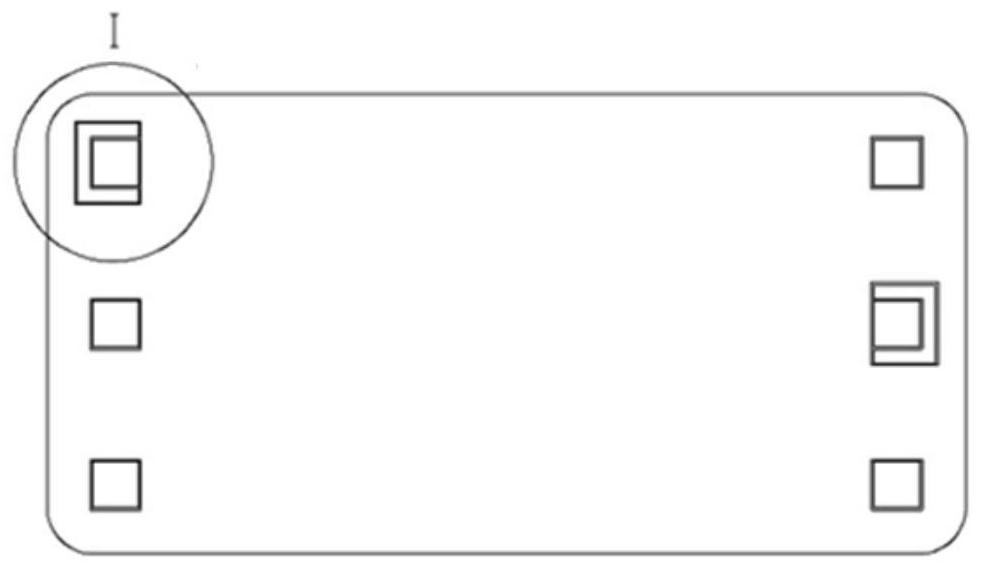
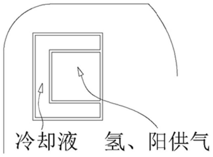
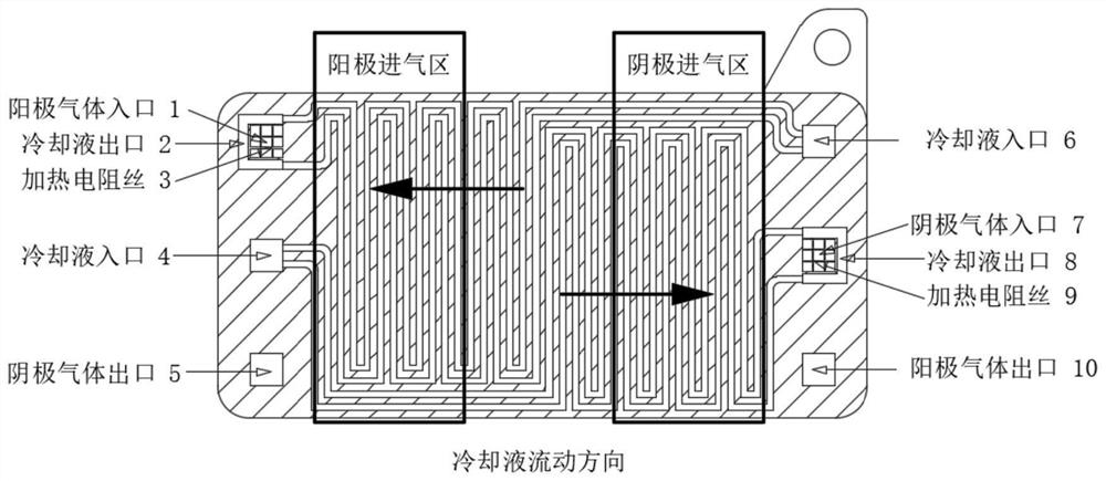
[0035] In one or more embodiments, a new type of fuel cell stack with intake air multi-stage self-preheating is disclosed. The hydrogen and oxygen gas supply in the stack includes three preheating stages. The first preheating method is to The outlet of the coolant flow channel in the stack is surrounded by the periphery of the intake manifold to form a sleeve-type intake manifold, and the coolant flows in the opposite direction to the intake fluid to form a counter-current convection heat exchange; the second stage preheating method is through dual The flow of coolant in the polar plate provides heat, and the coolant in the bipolar plate flows from the middle area of ​​the bipolar plate to the intake area on both sides, so that the hotter coolant flows in the intake area; the third stage preheating method is A resistance wire is installed in the intake manifold to realize the temperature regulation of the hydrogen and oxygen gas supply, forming a complete preheating process of ...

Embodiment 2

[0045] In one or more embodiments, a control method of a new type of fuel cell stack with intake air multi-stage self-preheating is disclosed. The method is based on the stack structure in Example 1; for specific methods, refer to Figure 8 , including the following process:

[0046] (1) First, calculate the preheated intake air temperature required for the required hydrogen and oxygen supply according to the existing working conditions of the fuel cell;

[0047] (2) Through the sleeve-type intake manifold, the residual heat of the coolant can convectively exchange heat with the fluid in the intake manifold;

[0048] (3) The intake area is heated by circulating coolant in the bipolar plate;

[0049] (4) Judging whether the gas temperature is lower than the required preheating intake temperature at this time, if it is lower, turn on the resistance wire heating; otherwise, turn it off.


PUM


Abstract

The invention discloses a novel fuel cell stack with inlet gas multistage self-preheating and a control method, the novel fuel cell stack comprises an inlet manifold, the inlet manifold comprises an anode gas inlet flow channel and a cathode gas inlet flow channel which are respectively arranged at two sides in the stack; a cooling liquid outlet flow channel is arranged on the periphery of the air inlet manifold in a surrounding mode, and a sleeve type air inlet manifold is formed. And the cooling liquid and the air inlet fluid flow in opposite directions to form counter-flow type convection heat exchange. The hydrogen and oxygen inlet gas is subjected to multi-stage preheating in the galvanic pile, the inlet gas temperature preheating target under different working conditions can be achieved, devices and power consumption required for heating the inlet gas outside the galvanic pile are reduced, a fuel cell system is more portable, and the total efficiency of a fuel cell is improved through step-by-step utilization of waste heat of cooling liquid.

Description

technical field [0001] The invention relates to the technical field of proton exchange membrane fuel cells, in particular to a novel fuel cell stack with intake air multi-stage self-preheating and a control method. Background technique [0002] The statements in this section merely provide background information related to the present invention and do not necessarily constitute prior art. [0003] Proton exchange membrane fuel cell is a device that can directly convert hydrogen fuel and chemical energy in the air into electrical energy. It has the advantages of high efficiency, no noise, and no pollution. The optimum operating temperature range of proton exchange membrane fuel cells is 60-80°C, within which the fuel cells can reach the maximum rated power. [0004] If the intake air is not preheated, the stack will be in a working state with a large temperature difference for a long time, which will accelerate the performance decay of the stack and reduce the service life. ...

Claims


Application Information

Patent Timeline
Patent Type & Authority Applications(China)
IPC IPC(8): H01M8/04029H01M8/2484H01M8/2483H01M8/0263H01M8/04007
CPCH01M8/04029H01M8/2484H01M8/2483H01M8/04037H01M8/0263
Inventor 高明张慧颖王宇航韩奎华何锁盈程星星齐建荟
Owner SHANDONG UNIV
Why Eureka
Try Eureka