Hydrogen purification device for fuel cell engine

A fuel cell and engine technology, applied in fuel cells, electrical components, electrochemical generators, etc., can solve the problems of complex purification device procedures, difficult adsorption control, unfavorable portability and movement, etc., to expand the source of hydrogen and adapt to a wide range of conditions , The effect of improving power generation efficiency

Pending Publication Date: 2022-05-10
BEIJING SINOHYTEC
View PDF0 Cites 0 Cited by
  • Summary
  • Abstract
  • Description
  • Claims
  • Application Information

AI Technical Summary

Problems solved by technology

[0004] In view of the above analysis, the embodiment of the present invention aims to provide a hydrogen purification device for fuel cell engines to solve the problems of existing purification devices with complex procedures, numerous equipment, unfavorable portability and difficulty in adsorption control

Method used


Image

  • Hydrogen purification device for fuel cell engine
  • Hydrogen purification device for fuel cell engine
  • Hydrogen purification device for fuel cell engine

Examples


Embodiment 1

[0050] An embodiment of the present invention discloses a hydrogen purification device for a fuel cell engine, including a solid-state electrochemical reactor and a controller.

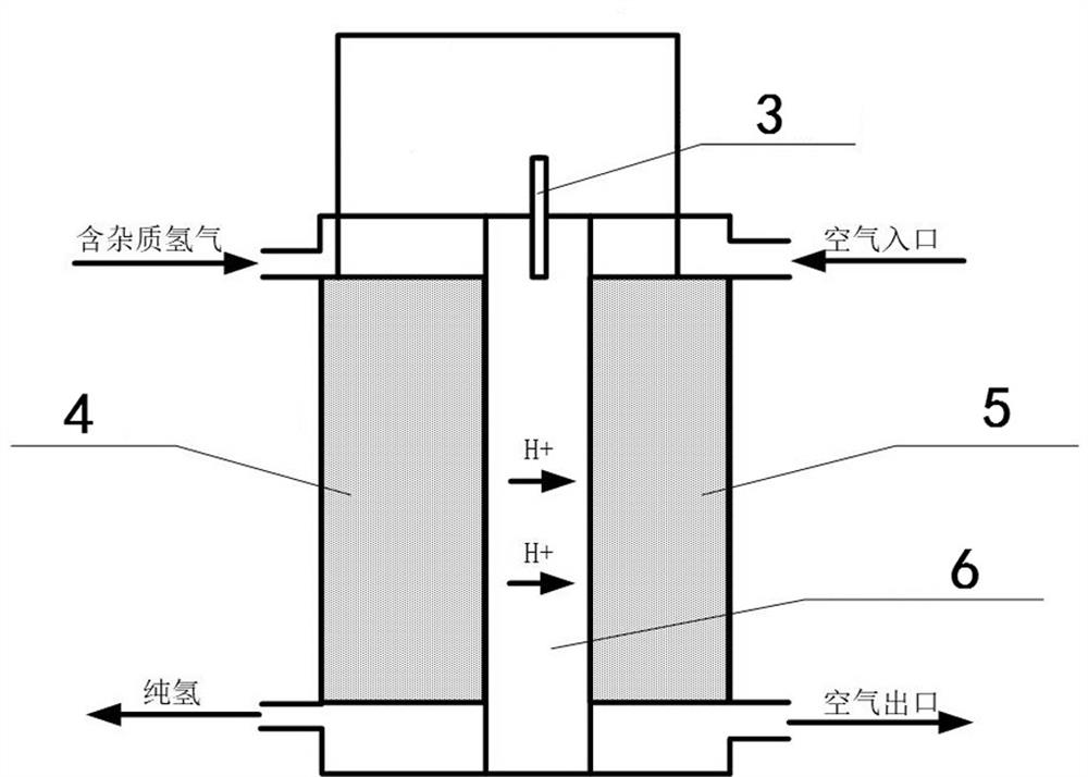
[0051] like figure 1 As shown, the solid state electrochemical reactor further includes an anode electrode layer 4 , an electrolyte layer 6 , a cathode electrode layer 5 and a reference electrode 3 . The anode electrode layer 4 is provided with a hydrogen inlet to be purified and a hydrogen outlet after purification; the cathode electrode layer 5 is provided with an air inlet and an air outlet; the electrolyte layer 6 is arranged between the anode electrode layer 4 and the cathode electrode layer 5; the reference electrode 3 is arranged on Inside the electrolyte layer 6; the anode electrode layer 4 and the cathode electrode layer 5 can be connected by external wires.

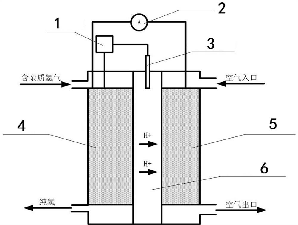
[0052] The output terminal of the controller is respectively connected with the anode electrode layer 4, the cathode electrode layer ...

Embodiment 2

[0064] Improvement is made on the basis of Example 1. For CO impurities, the potential of the anode electrode layer 4 is 0.8~0.9V, the operating temperature of the solid-state electrochemical reactor is 50~80°C, the inlet of the hydrogen to be purified and the air The inlet gas temperature is 0~40℃, the gas pressure is 100~250 kPa, and the gas humidity is 20~100% RH.

[0065] Preferably, both the anode electrode layer 4 and the cathode electrode layer 5 adopt a porous carbon structure with catalysts distributed on the surface. Specifically, porous carbon with surface-distributed catalysts is used as the base material, proton-conducting ionomer is used as the binder, and carbon fibers are used as the skeleton to construct a porous electrode capable of transporting gas and protons.

[0066] Preferably, the catalyst of the anode electrode layer 4 is a composite of metal oxide and platinum, which can improve the selectivity of the catalyst to CO, such as titanium oxide (TiO). The...


PUM


Abstract

The invention provides a hydrogen purification device for a fuel cell engine, belongs to the technical field of fuel cells, and solves the problems that an existing purification device is complex in process, various in equipment, not convenient to carry and move and high in adsorption control difficulty. The device comprises a solid-state electrochemical reactor and a controller. Wherein the solid-state electrochemical reactor further comprises an anode electrode layer, an electrolyte layer, a cathode electrode layer and a reference electrode; the anode electrode layer is provided with a to-be-purified hydrogen inlet and a purified hydrogen outlet; the cathode electrode layer is provided with an air inlet and an air outlet; the electrolyte layer is arranged between the anode electrode layer and the cathode electrode layer; and the reference electrode is arranged in the electrolyte layer. The controller is used for controlling the working temperature of the solid-state electrochemical reactor and the humidity and pressure of hydrogen to be purified, and the anode voltage is set as the oxidation-reduction potential of impurities. The device utilizes an electrochemical principle to carry out hydrogen online purification, and can be applied to most fuel cell systems at present.

Description

technical field [0001] The invention relates to the technical field of fuel cells, in particular to a hydrogen purification device for fuel cell engines. Background technique [0002] Fuel cell engines use hydrogen as fuel to convert chemical energy into electrical energy through electrochemical reactions. Due to the slow electrode kinetics, a catalyst is needed to accelerate the reaction, such as platinum metal. At present, the source of hydrogen is mainly industrial by-product hydrogen, such as reforming hydrogen production. The gas source often contains CO impurities. A small amount of CO can cause catalyst poisoning and reduce the performance of fuel cell engines. In the hydrogen purity requirements stipulated by the Hydrogen Energy Technical Committee of the International Organization for Standardization, the concentration of carbon monoxide should not be higher than 0.2 ppm. [0003] Among the existing hydrogen purification methods, the most widely used method is pre...

Claims


Application Information

Patent Timeline
Patent Type & Authority Applications(China)
IPC IPC(8): H01M8/0656B01D53/32
CPCH01M8/0656B01D53/32B01D2257/502B01D2256/16
Inventor 曹季冬方川李飞强
Owner BEIJING SINOHYTEC
Why Eureka
Try Eureka