Rapid preparation method of flexible conductive circuit board
A conductive circuit and flexible conductive technology, which is applied in the field of rapid preparation of flexible conductive circuit boards, can solve problems such as difficult rapid preparation of thicker circuits, restrictions on the development and application of flexible conductive circuit boards, and poor bonding between coatings and substrates. The effect of fast forming speed, good bonding strength and high utilization rate
- Summary
- Abstract
- Description
- Claims
- Application Information
AI Technical Summary
Problems solved by technology
Method used
Image

Examples
Embodiment 1
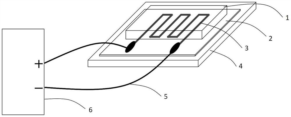
[0024] A picosecond laser was used to cut a conductive line with a width of 1mm on a copper sheet with a thickness of 0.03mm; a polyethylene terephthalate substrate was placed on a glass sheet. Place the conductive circuit on the surface of the polyethylene terephthalate material and press it tightly with a glass sheet; connect the positive and negative poles of the power supply at both ends of the conductive circuit. The input current is 3-5A, and it is kept for a short time of 1-3s. The surface of the substrate in contact with the conductive lines undergoes momentary melting, and the conductive lines combine with the flexible substrate to form the final conductive circuit board.
[0025] The forming speed of the conductive circuit is fast, the operation process is simple, no complicated chemical treatment is required, the invention is environmentally friendly, the material utilization rate is high, and the bonding strength of the circuit and the substrate is good.
Embodiment 2
[0027] Conductive lines were prepared by mechanical bending using a copper wire with a diameter of 0.1 mm; a polyethylene terephthalate substrate was placed on a glass slide. Place the conductive circuit on the surface of the polyethylene terephthalate material, and press it tightly with a glass sheet; connect the positive and negative electrodes of the power supply at both ends of the conductive circuit; pass in a current of 5-7A, and keep it for 1-3s A short time; the surface of the substrate in contact with the copper wire melts momentarily, and the copper wire combines with the flexible substrate to form the final conductive circuit board.
[0028] The conductive circuit prepared by the above method has fast forming speed, simple operation process, no complicated chemical treatment, environmental protection, high copper utilization rate, and good bonding strength between the circuit and the substrate.
PUM
| Property | Measurement | Unit |
|---|---|---|
| Width | aaaaa | aaaaa |
| Thickness | aaaaa | aaaaa |
| Diameter | aaaaa | aaaaa |
Abstract
Description
Claims
Application Information
 - Generate Ideas
- Intellectual Property
- Life Sciences
- Materials
- Tech Scout
- Unparalleled Data Quality
- Higher Quality Content
- 60% Fewer Hallucinations
Browse by: Latest US Patents, China's latest patents, Technical Efficacy Thesaurus, Application Domain, Technology Topic, Popular Technical Reports.
© 2025 PatSnap. All rights reserved.Legal|Privacy policy|Modern Slavery Act Transparency Statement|Sitemap|About US| Contact US: help@patsnap.com