
Heat pipe heat exchange device, heat exchange system and temperature regulation control method

A heat pipe heat exchange and heat exchange system technology, applied in indirect heat exchangers, lighting and heating equipment, cooling/ventilation/heating transformation, etc., can solve the problem of increasing the air supply volume of air conditioners, poor air flow organization, and increasing the operation of air conditioning systems Energy consumption and other issues to achieve the effect of improving heat dissipation efficiency and avoiding adverse effects

Pending Publication Date: 2022-05-13
CHINA UNITED NETWORK COMM GRP CO LTD
View PDF0 Cites 1 Cited by
  • Summary
  • Abstract
  • Description
  • Claims
  • Application Information

AI Technical Summary

Problems solved by technology

[0004] However, this air-cooling system has the following obvious defects: First, due to the poor heat transfer performance of the air, a lower air supply temperature is required to ensure the normal operation of the high heat density server, which will increase the operating energy consumption of the air conditioning system , resulting in an increase in the heat dissipation energy consumption of the existing data center; second, due to the narrow space in the cabinet and poor airflow organization, it is easy to cause local high-temperature hot spots in the cabinet, which affects the safe operation of IT equipment such as servers. In order to eliminate local hot spots, often It is achieved by increasing the air supply volume of the air conditioner and reducing the temperature of the air supply, which leads to a further increase in energy consumption of the air conditioning system; third, because the data center has high requirements for the cleanliness of the air, long-term air flow will cause dust Substances such as sulfur oxides and nitrogen oxides adhere to the electronic components of the server, resulting in an increase in the failure rate of the server and a shortened service life.

Method used


Image

  • Heat pipe heat exchange device, heat exchange system and temperature regulation control method
  • Heat pipe heat exchange device, heat exchange system and temperature regulation control method
  • Heat pipe heat exchange device, heat exchange system and temperature regulation control method

Examples


Embodiment Construction

[0033] The following will clearly and completely describe the technical solutions in the embodiments of the present invention with reference to the accompanying drawings in the embodiments of the present invention. Obviously, the described embodiments are only some, not all, embodiments of the present invention. Based on the embodiments of the present invention, all other embodiments obtained by persons of ordinary skill in the art without making creative efforts belong to the protection scope of the present invention.

[0034] In describing the present invention, it is to be understood that the terms "center", "upper", "lower", "front", "rear", "left", "right", "top", "bottom", " The orientation or positional relationship indicated by "inner", "outer", etc. is based on the orientation or positional relationship shown in the drawings, which is only for the convenience of describing the present invention and simplifying the description, rather than indicating or implying that th...


PUM


Abstract

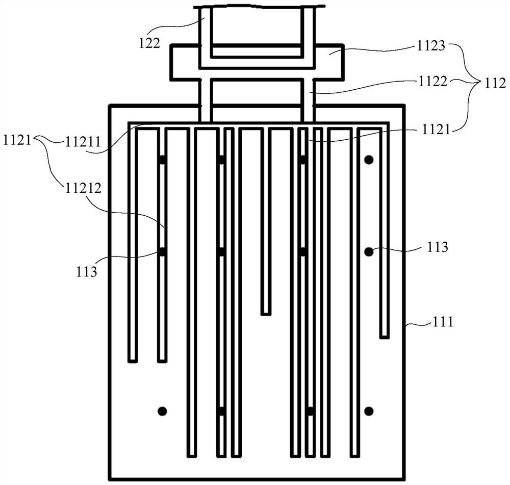
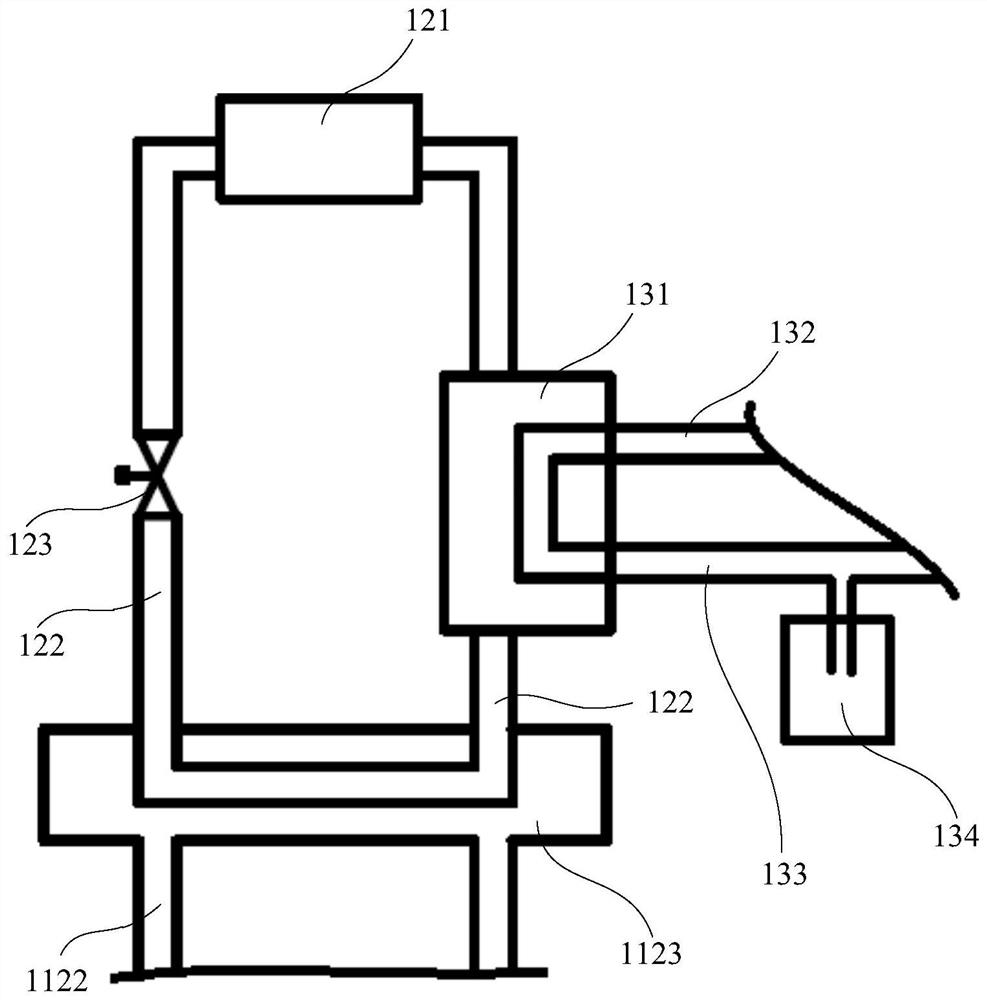
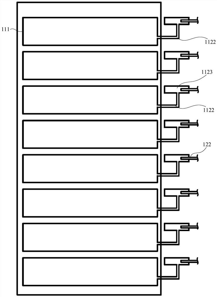
The invention discloses a heat pipe heat exchange device, a heat exchange system and a temperature regulation control method, relates to the technical field of liquid cooling devices, can greatly improve the heat dissipation efficiency of a cabinet, ensures the uniformity of the temperature in the cabinet while realizing high-temperature heat dissipation, and also avoids the adverse effect of particulate matters in the air on a server. The heat pipe heat exchange device comprises a first shell and a heat pipe heat exchanger, a closed space is formed in the first shell, a heating element and cooling liquid are arranged in the first shell, a circulating first refrigerant circulates in the heat pipe heat exchanger, the heat pipe heat exchanger comprises an evaporation section and a condensation section, the evaporation section is located in the closed space and is close to the heating element, and the condensation section is located in the closed space. The condensation section is located outside the closed space, and the heating element and the evaporation section are immersed in the cooling liquid.

Description

technical field [0001] The invention relates to the technical field of liquid cooling devices, in particular to a heat pipe heat exchange device, a heat exchange system and a control method for temperature adjustment. Background technique [0002] The data center (Internet Data Center, Internet Data Center, referred to as IDC) computer room has become an important part of economic development, and is the infrastructure for promoting the informatization and digitization of technology and industry. With the increase in the scale of data centers and the popularity of blade servers with high heating power, the installed power and heat density of cabinets in data centers have increased sharply. On the one hand, the heat dissipation of high heat density servers has become an urgent problem to be solved. If you are careful, the equipment may be shut down due to overheating, causing huge losses; on the other hand, the power of cooling equipment required for heat dissipation will inc...

Claims


Application Information

Patent Timeline
Patent Type & Authority Applications(China)
IPC IPC(8): F28D15/02F28D15/04F28D15/06H05K7/20
CPCF28D15/02F28D15/04F28D15/06H05K7/208
Inventor 闫健
Owner CHINA UNITED NETWORK COMM GRP CO LTD
Learn More