Laser welding equipment and method for drying towel rack
A laser welding and laser welding machine technology, which is applied in laser welding equipment, welding equipment, metal processing equipment, etc., can solve the problems that welding cannot meet the needs, high-frequency electromagnetic radiation, slag inclusion and missing welding, etc., and achieve process versatility The effect of high utilization rate of equipment and equipment, improvement of solder plasticity and quality, and reduction of welding cost
- Summary
- Abstract
- Description
- Claims
- Application Information
AI Technical Summary
Problems solved by technology
Method used
Image
Examples
Embodiment 1
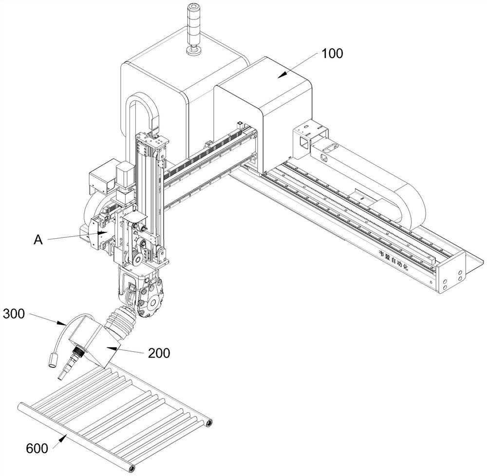
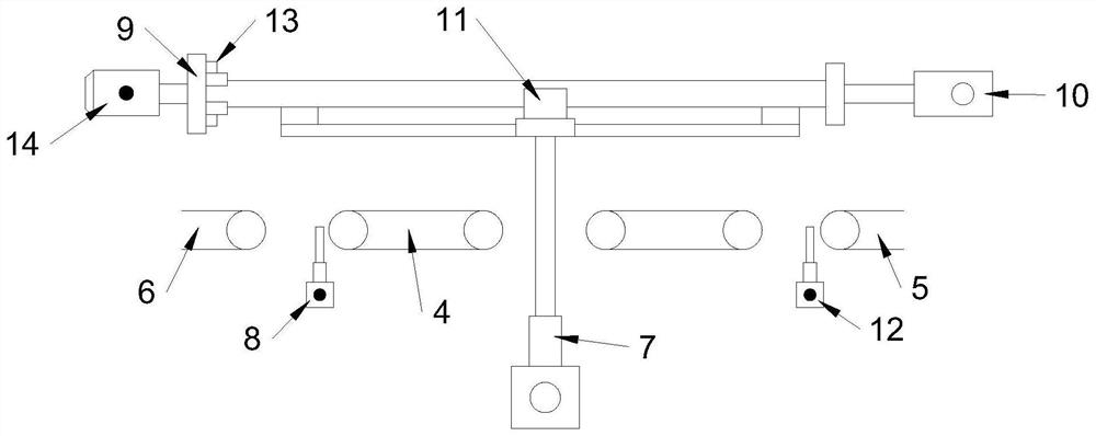
[0055] Reference attached Figure 3-4 After welding, the towel rack is lowered to the initial intermediate conveying device 4, and the intermediate conveying device transmits the towel rack to the feeding conveying device 6, and then the next towel rack to be welded enters the intermediate conveying device 4 and then performs the next welding cycle.
[0056] The first partition L 1A first material blocking mechanism 12 consistent with the structure of the second material blocking mechanism 8 is provided at the place, which is used to block the towel rack on the incoming material conveying device 5 from continuing to advance during the welding process, so as to prevent the lifting mechanism 7 from being lowered after welding. When the towel rack is stacked with the incoming material towel rack, the unwelded towel rack is omitted. In the process, the time required for welding is matched with the time of the incoming material to avoid the gradual increase of the towel rack retain...
Embodiment 2
[0065] Reference attached Figure 9 , on the basis of embodiment 1, the difference between the welding method in this embodiment and the welding method of embodiment 1 is only:
[0066] Step S3, laser welding: the lifting mechanism 7 moves down to a predetermined height to provide space for the towel rack to turn over, and the laser welding machine 200 performs continuous laser welding on the position to be welded on one side of the towel rack under the preset program of the three-dimensional adjustment platform 100, Then, the longitudinal positioning cylinder 10 resets, the motor 14 drives the towel rack to turn over 180°, and the longitudinal positioning cylinder 10 moves again to clamp the towel rack. The laser welding machine 200 continues to continuously laser weld the unwelded side, and the visual tracking system 300 Track the welding position and display the welding process on the computer monitor, and reset the laser welding machine to the top of the towel rack after w...
Embodiment 3
[0070] Reference attached Figure 10 , for the situation that the rate of incoming material is greater than the rate of laser welding of a single towel rack, in the schemes of embodiments 1 and 2, the number of follow-up incoming towel racks that are blocked by the first material blocking mechanism 12 gradually increases, and accumulates on the incoming material conveying device 5, that is, the single laser welding machine 200 is the bottleneck of the process, and it is not applicable to the production line where the pre-order assembly process speed is greater than the welding speed. Based on this, in this embodiment, multiple laser welding machines 200 are installed on the same conveying device to compensate for the drying rate.
[0071] On the basis of Embodiment 2, the output of the jacking cylinder 701 is connected to the side of the jacking platform 702, that is, the output rod of the jacking cylinder 701 is located at the side of the intermediate transmission device 4, t...
PUM
 Abstract
Description
Claims
Application Information
 - R&D
- Intellectual Property
- Life Sciences
- Materials
- Tech Scout
- Unparalleled Data Quality
- Higher Quality Content
- 60% Fewer Hallucinations
Browse by: Latest US Patents, China's latest patents, Technical Efficacy Thesaurus, Application Domain, Technology Topic, Popular Technical Reports.
© 2025 PatSnap. All rights reserved.Legal|Privacy policy|Modern Slavery Act Transparency Statement|Sitemap|About US| Contact US: help@patsnap.com


