Automatic production process of intelligent manufacturing beam field

A production process and intelligent manufacturing technology, which is applied in the manufacture of tools, bridges, bridge parts, etc., can solve the problems of difficult to meet higher requirements, concrete honeycomb pitted surface, low vibration effect, etc., to achieve improved appearance and fast cycle operation , The effect of saving the consumption of human resources

Pending Publication Date: 2022-05-27
GUANGDONG PROVINCIAL CHANGDA HIGHWAY ENG
View PDF13 Cites 0 Cited by
  • Summary
  • Abstract
  • Description
  • Claims
  • Application Information

AI Technical Summary

Problems solved by technology

[0002] In expressways, prefabricated girders and slabs account for about 80% of bridge engineering, and the production of girders and slabs is more about the production of raw materials, erection of girder and slab steel reinforcement skeletons, installation of girder and slab formwork, concrete pouring, maintenance, prestressed tensioning, etc. The area is relatively scattered, and the corresponding products need to be produced in each production area before being transported to the next production area for further production and production work. However, this type of production technology occupies a large area and has a long production period, which is difficult to meet large-scale assembly. Engineering puts forward higher requirements for the production of prefabricated components
Traditional concrete pouring vibrators include plug-in type, attached type, and flat-plate type. Due to the need for manual operation, it is difficult to accurately grasp the vibration frequency, vibration time, and vibration position. There are phenomena such as honeycomb pitting and leaking ribs, and the vibrating effect of workers is low and the construction period is long

Method used


Image

  • Automatic production process of intelligent manufacturing beam field
  • Automatic production process of intelligent manufacturing beam field
  • Automatic production process of intelligent manufacturing beam field

Examples


Embodiment Construction

[0052] The technical solutions in the embodiments of the present invention will be clearly and completely described below with reference to the accompanying drawings in the embodiments of the present invention. Obviously, the described embodiments are only a part of the embodiments of the present invention, but not all of the embodiments. Based on the embodiments of the present invention, all other embodiments obtained by those of ordinary skill in the art without creative efforts shall fall within the protection scope of the present invention.

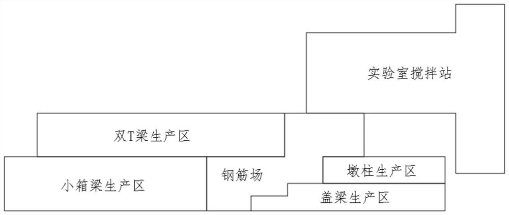
[0053] see figure 1 As shown, the present invention is an intelligent manufacturing beam field automated production process, comprising the following steps:

[0054] Step 1. Divide the manufacturing beam yard into areas, namely small box girder production area, double T beam production area, cover beam production area, pier column production area, steel bar yard and laboratory mixing station, and the steel bar yard is the same as the ...


PUM


Abstract

The invention discloses an automatic production process of an intelligent manufacturing beam yard, which comprises the following steps: step 1, the manufacturing beam yard is divided into a small box beam production area, a double-T beam production area, a cover beam production area, a pier stud production area, a steel bar yard and a laboratory mixing plant, and the steel bar yard is connected with the other five areas; secondly, annular production lines are arranged in the small box beam production area, the double-T-beam production area, the cover beam production area and the pier column production area and used for production of the bridge prefabricated parts; thirdly, a movable trolley is adopted in the annular production line to achieve production transfer, and integral vibration tables without manual vibration are adopted in the double-T-beam production area and the bent cap production area to achieve pouring vibration construction; the device has the advantage of fast circulation operation, improves the production efficiency, saves the consumption of human resources, saves the workshop space, and fundamentally saves the cost investment.

Description

technical field [0001] The invention relates to the technical field of bridge component prefabrication, in particular to an automated production process for intelligently manufactured beam fields. Background technique [0002] In the expressway, prefabricated beams and slabs account for about 80% of the bridge engineering, and the production of beams and slabs is more about the production of raw materials, the erection of beam-slab steel skeletons, the installation of beam-slab formwork, concrete pouring, maintenance, prestressed tensioning, etc. The area is relatively scattered, and it is necessary to complete the corresponding products in each production area before transporting it to the next production area for further production work. However, such production technology occupies a large area and has a long production period, which is difficult to meet the needs of large-scale assembly. Engineering puts forward higher requirements for the production of prefabricated comp...

Claims


Application Information

Patent Timeline
IPC IPC(8): B28B23/04B28B23/02B28B1/087E01D19/00E01D101/26
CPCB28B23/043B28B23/024B28B1/0873E01D19/00E01D2101/26Y02P90/02
Inventor 刘宏波刘志峰邓文豪苏年就林文朴胡典亮
Owner GUANGDONG PROVINCIAL CHANGDA HIGHWAY ENG
Why Eureka
Try Eureka