Clamping device for laser cladding of engine connecting rod and connecting rod repairing method
A technology of engine connecting rod and laser cladding, which is applied in the coating, metal material coating process, etc., can solve the problems that it is difficult to control the surface roughness and dimensional accuracy of the coating, and does not meet the environmental impact assessment occupational hazard assessment, etc., to improve Effects of restoration efficiency and quality, improvement of restoration efficiency, and simplification of secondary processing
- Summary
- Abstract
- Description
- Claims
- Application Information
AI Technical Summary
Problems solved by technology
Method used
Image
Examples
Embodiment 1
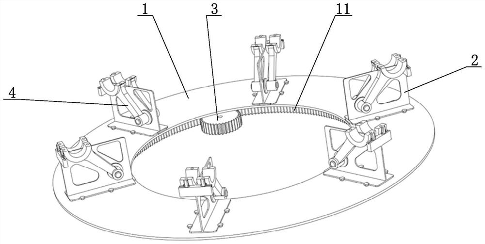
[0055] as Figure 1 、 Figure 2 and Figure 5 Commonly shown, a clamping device for engine connecting rod laser cladding repair, including: turntable 1 and multiple circumferentially distributed fixtures mounted on the turntable 2;
[0056] The turntable 1 is fixed with a ring of gear 11, the ring of gear 11 meshes with the drive gear 3, the drive gear 3 is driven by a motor device, and the motor device is a motor or a motor driven reducer;
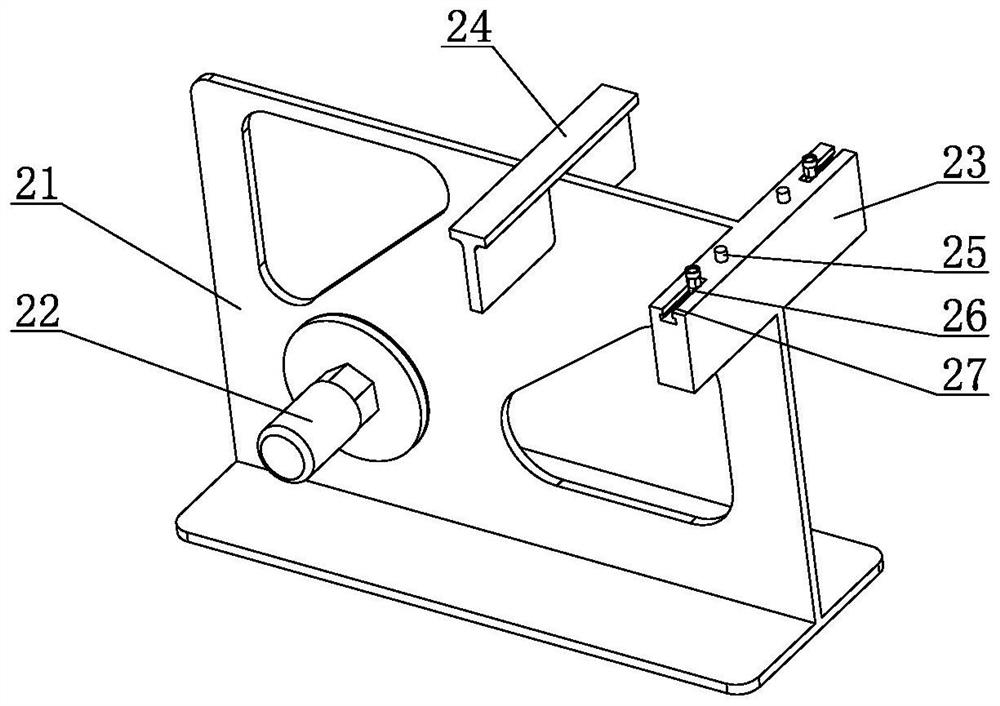
[0057] Fixture 2 includes a T-bracket 21, a positioning shaft 22, a fixed support block 23 and a plug-in support block 24, a T-type bracket 21 is inverted fixed to the turntable 1, a fixed support block 23 and a positioning axis 22 is fixed to the T-bracket 21, the fixed support block 23 is located obliquely above the positioning axis 22, the fixed support block 23 is provided with a positioning pin group, when the clamping link cover 5, the insertion support block 24 is mounted on the T-type bracket.
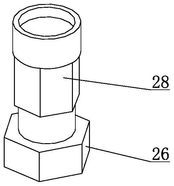
[0058] The positioning pin group includes ...
Embodiment 2
[0062] An engine linkage laser cladding repair method, characterized in that it comprises the following steps:
[0063] S1. Collect the connecting rod to be repaired in batches, measure the inner diameter of each connecting rod head hole from four directions and record it, and compare the maximum deviation diameter. The angle between the two adjacent directions is 45°, and the diameter of the large head hole can also be measured from six or eight directions.
[0064] S2, boring and milling of the deformation layer of the large head hole, boring and milling volume is greater than the maximum deviation diameter, in order to completely remove the amount of deformation.
[0065] S3. Clean the processing surface with anhydrous alcohol, remove impurities such as oxides and oil stains, and remove the oil and sediment left in the oil channel thoroughly.
[0066] S4: Fill the connecting rod tile groove holes with sand clay and press the shape with a spatula to clean up the excess clay. San...
PUM
 Abstract
Description
Claims
Application Information
 - R&D
- Intellectual Property
- Life Sciences
- Materials
- Tech Scout
- Unparalleled Data Quality
- Higher Quality Content
- 60% Fewer Hallucinations
Browse by: Latest US Patents, China's latest patents, Technical Efficacy Thesaurus, Application Domain, Technology Topic, Popular Technical Reports.
© 2025 PatSnap. All rights reserved.Legal|Privacy policy|Modern Slavery Act Transparency Statement|Sitemap|About US| Contact US: help@patsnap.com


