Ceramic shell for single-crystal high-temperature alloy blade and preparation method of ceramic shell

A high-temperature alloy, ceramic type technology, applied in the field of investment casting, can solve the problems of increasing the amount of slurry and sand and prolonging the cycle of ceramic shells, and achieves the effect of reducing the amount of consumption, shortening the production cycle, and improving the ease of release.

Pending Publication Date: 2022-06-03
SHANGHAI UNIV
0 Cites 0 Cited by

AI-Extracted Technical Summary

Problems solved by technology

However, as the number of layers of slurry coating increases, it will directly lead to the extension of...

Method used

[0063] In the present invention, the width of the carbon fiber cloth is preferably 8-12cm, more preferably 10cm; the thickness of the carbon fiber is preferably 0.110-0.112mm, more preferably 0.111mm. In the present invention, there is no special regulation on the source of the carbon fiber cloth, and commercially available products well known to those skilled in the art can be used. In the present invention, the wrapping method is preferably spiral wrapping. The present invention adopts a spiral wrapping method, which can realize the tight combination of the fiber cloth and the outer surface of the third composite structure. In the present invention, after the preparation of the three layers is completed, epoxy resin is coated on the surface of the ceramic shell, and a layer of carbon fiber cloth tape is wrapped, so that in the later firing process, the epoxy resin...

Abstract

The invention relates to the technical field of investment casting, and provides a preparation method of a ceramic shell for a single-crystal high-temperature alloy blade, when the ceramic shell is prepared, after three layers are prepared, the surface of the ceramic shell is coated with epoxy resin, and then is wrapped with a layer of carbon fiber cloth tape, so that in the later roasting process, the surface of the ceramic shell is coated with a layer of carbon fiber cloth tape; the epoxy resin can generate residual carbon under the condition of relatively high temperature, and forms a C-C interconnected interwoven structure with good mechanical properties with the carbon fiber cloth, so that the strength of the shell is enhanced, and the number of layers of coated slurry is reduced; after the three-layer shell is prepared, carbon fiber cloth is wrapped, and the situation that the alloy performance is affected due to the fact that the carbon fiber cloth reacts with metal alloy liquid in the casting process is effectively avoided. According to the ceramic shell disclosed by the invention, the number of layers of coated slurry is reduced, so that the manufacturing period of the shell is shortened, and the use amount of the slurry and gravel is reduced.

Application Domain

Technology Topic

Image

  • Ceramic shell for single-crystal high-temperature alloy blade and preparation method of ceramic shell
  • Ceramic shell for single-crystal high-temperature alloy blade and preparation method of ceramic shell
  • Ceramic shell for single-crystal high-temperature alloy blade and preparation method of ceramic shell

Examples

  • Experimental program(2)
  • Comparison scheme(1)
  • Effect test(1)

Example Embodiment

[0035] The invention provides a preparation method of a ceramic shell for a single crystal superalloy blade, comprising the following steps:
[0036] (1) carry out surface layer slurry coating, sanding and drying on the outer surface of the wax mold to obtain the first composite structure after preparing the surface layer;
[0037] (2) on the outer surface of the first composite structure obtained in the step (1), the transition layer slurry coating, sanding and drying are performed to prepare the transition layer to obtain the second composite structure;
[0038] (3) on the outer surface of the second composite structure obtained in the step (2), carry out the back layer slurry coating, sanding and drying to prepare the first back layer to obtain the third composite structure;
[0039] (4) coating the outer surface of the third composite structure obtained in the step (3) with epoxy resin, and then wrapping a layer of carbon fiber tape on the outer surface of the epoxy resin coated outer surface and drying to obtain a fourth composite structure ;
[0040] (5) on the outer surface of the fourth composite structure obtained in the step (4), repeat the operation of the step (4) n times to prepare the n+1th back layer to obtain a fifth composite structure, where n≥1;
[0041] (6) carrying out slurry sealing treatment on the outer surface of the fifth composite structure obtained in the step (5) to obtain a ceramic shell that has been coated and hung;
[0042] (7) dewaxing the coated ceramic shell obtained in the step (6) to obtain a ceramic shell precursor;
[0043] (8) calcining the ceramic shell precursor obtained in the step (7) to obtain a ceramic shell for a single crystal superalloy blade.
[0044] In the present invention, the surface layer slurry is coated, sanded and dried on the outer surface of the wax mold, and the first composite structure is obtained after the surface layer is prepared.
[0045] The present invention has no special provisions on the wax mold, and a wax mold well-known to those skilled in the art for preparing a ceramic shell can be used. In the present invention, the wax model is preferably washed and dried in sequence before use. The present invention has no special provisions on the cleaning, and the cleaning method well-known to those skilled in the art can be used to clean the residual oil stains and other impurities on the outer surface of the wax mold. The present invention does not specifically stipulate the drying method, and the drying method well-known to those skilled in the art can be used to remove the residual reagents when washing the wax mold. In the present invention, the wax mold plays the role of supporting and shaping the material in the process of preparing the ceramic shell.
[0046] In the present invention, the surface layer slurry is preferably a mixture of silica sol and brown corundum sand. In the present invention, the viscosity of the surface layer slurry is preferably 2.8-3.4 MPa.s, more preferably 3.0-3.3 MPa.s. In the embodiment of the present invention, the viscosity of the surface layer slurry is preferably 3.2 MPa.s. The present invention does not specifically stipulate the dosage relationship between the silica sol and the brown corundum sand, and the brown corundum sand can be adjusted to the required slurry viscosity by using the silica sol. In the present invention, the particle size of the brown corundum sand in the surface layer slurry is preferably 310-330 mesh, more preferably 320 mesh. The present invention has no special provisions on the sources of the silica sol and brown corundum sand, and the silica sol and brown corundum sand well known to those skilled in the art can be used. The invention selects brown corundum sand with strong fluidity, low coefficient of linear expansion and corrosion resistance to mix with silica sol to prepare a surface layer slurry with a certain viscosity, and the obtained ceramic shell has better comprehensive performance. In the present invention, the viscosity of the surface layer slurry is limited to the above range, which is beneficial to the coating and hanging of the surface layer slurry.
[0047] The present invention has no special provisions on the method of coating and hanging. The coating and hanging method well known to those skilled in the art is used to coat the surface layer slurry on the outer surface of the wax mold, and the slurry can flow naturally under the action of gravity.
[0048]In the present invention, when preparing the surface layer, the sand in the sand sprinkler is preferably brown corundum sand. In the present invention, brown corundum sand with strong fluidity, low linear expansion coefficient and corrosion resistance can be selected to meet the requirements for the performance of ceramic shells when preparing single crystal superalloy blades. The particle size of the sand in the sand spreading is preferably 60-80 mesh, more preferably 65-75 mesh. The present invention has no special provisions on the sand spreading operation, and the sand spreading method well known to those skilled in the art can be used to spread the required sand and gravel on the surface of the surface layer. The present invention does not specifically stipulate the amount of sand in the sand spreading. The sand is spread on the surface of the product coated with the surface layer slurry by the sand spreading method well known to those skilled in the art, and the sand and gravel can be distributed in a single layer. In the present invention, the thickness of a single surface layer is mainly determined by the particle size of the sand on which the sand is sprinkled. In the present invention, when preparing the surface layer, the particle size of the sand in the spreading sand is limited to the above-mentioned range, which can meet the requirement of preparing the required surface layer thickness.
[0049] The present invention does not specifically stipulate the drying method when preparing the surface layer. After the sand-spraying operation is completed, the wax mold after the sand-spraying treatment can be naturally dried at room temperature.
[0050] After obtaining the first composite structure, according to the present invention, on the outer surface of the first composite structure, the transition layer slurry is coated, sanded and dried to prepare the transition layer to obtain the second composite structure, so that the number of layers is two layers. ceramic shell precursors.
[0051] In the present invention, the transition layer slurry is preferably the same as the material used for the surface layer slurry in the above solution, the only difference being that the viscosity of the transition layer slurry is lower than that of the surface layer slurry. In the present invention, the viscosity of the transition layer slurry is preferably lower than the viscosity of the surface layer slurry by 0.05-0.2 MPa.s; in the embodiment of the present invention, the viscosity of the surface layer slurry is selected to be 3.2 MPa.s On the basis of , the viscosity of the transition layer slurry is preferably 3.1 MPa.s. In the present invention, the viscosity of the transition layer slurry is limited to the above range, which is beneficial to the coating and hanging of the transition layer slurry.
[0052] In the present invention, when the transition layer is prepared, the coating and hanging method is preferably the same as the coating and hanging method when the surface layer is prepared.
[0053] In the present invention, when preparing the transition layer, the sand in the spreading sand is preferably the same as the sand used in preparing the surface layer; the particle size of the sand in the spreading sand is preferably 30-60 mesh, more preferably 40-50 mesh eye. When the transition layer is prepared in the present invention, the sand-spraying operation is the same as the sand-spraying operation when the surface layer is prepared. In the present invention, when preparing the transition layer, the particle size of the sand in the spreading sand is limited to the above-mentioned range, which can meet the requirement of preparing the required thickness of the transition layer.
[0054] In the present invention, when the transition layer is prepared, the drying method is the same as the drying method when the surface layer is prepared.
[0055] After the third composite structure is obtained, according to the present invention, the outer surface of the third composite structure is coated with the back layer slurry, sanded and dried to prepare the first back layer to obtain the fourth composite structure.
[0056] In the present invention, the back layer slurry is preferably the same as the material used for the transition layer slurry in the above solution, the only difference being that the viscosity of the back layer slurry is lower than that of the transition layer slurry. In the present invention, the viscosity of the back layer slurry is preferably lower than the viscosity of the transition layer slurry by 0.05-0.2 mPa.s. In the embodiment of the present invention, on the basis that the viscosity of the transition layer slurry is selected to be 3.1 mPa.s, the viscosity of the back layer slurry is preferably 3.0 mPa.s. In the present invention, the viscosity of the back layer slurry is limited to the above range, which is beneficial to the coating and hanging of the back layer.
[0057] In the present invention, when the back layer is prepared, the coating and hanging method is the same as the coating and hanging method when the transition layer is prepared.
[0058] In the present invention, when preparing the backing layer, the sand in the spreading sand is preferably the same as the sand used in preparing the surface layer; the particle size of the sand in the spreading sand is preferably 16-30 mesh, more preferably 20-25 mesh eye. When the backing layer is prepared in the present invention, the sand-spraying operation is the same as the sand-spraying operation when the transition layer is prepared. In the present invention, when preparing the backing layer, the particle size of the sand in the spreading sand is limited to the above-mentioned range, which can meet the requirement of preparing the required backing layer thickness.
[0059] In the present invention, when the back layer is prepared, the drying method is the same as the drying method when the transition layer is prepared.
[0060] After the third composite structure is obtained, the present invention coats the outer surface of the third composite structure with epoxy resin, and then wraps a layer of carbon fiber tape on the outer surface of the epoxy resin-coated third composite structure and then dries it. , the fourth composite structure is obtained.
[0061] The present invention does not specifically stipulate the source of the epoxy resin, and a commercially available product well known to those skilled in the art can be used.
[0062] The present invention has no special provisions on the coating operation, and the epoxy resin can be uniformly coated on the outer surface of the third composite structure by using a coating method well known to those skilled in the art. The present invention does not specifically stipulate the amount of the epoxy resin, as long as the outer surface of the third composite structure can be uniformly coated.
[0063] In the present invention, the width of the carbon fiber cloth is preferably 8-12 cm, more preferably 10 cm; the thickness of the carbon fiber is preferably 0.110-0.112 mm, more preferably 0.111 mm. The present invention does not specifically stipulate the source of the carbon fiber cloth, and a commercially available product well known to those skilled in the art can be used. In the present invention, the wrapping method is preferably spiral wrapping. In the present invention, the method of spiral wrapping can realize the close combination of the fiber cloth and the outer surface of the third composite structure. In the present invention, after the three-layer preparation is completed, the surface of the ceramic shell is coated with epoxy resin, and then wrapped with a layer of carbon fiber tape, so that in the later roasting process, the epoxy resin will generate carbon residue under a relatively high temperature condition. And it forms a C-C interwoven structure with good mechanical properties with carbon fiber cloth, thereby enhancing the strength of the shell and reducing the number of layers of coating and hanging slurry.
[0064] In the present invention, when preparing the fourth composite structure, the drying method is the same as the drying method when preparing the back layer.
[0065] After the fourth composite structure is obtained, the present invention repeats the operation of preparing the back layer n times on the outer surface of the fourth composite structure to prepare the n+1th back layer to obtain the fifth composite structure, where n≧1. In the present invention, after obtaining the fourth composite structure, at least one back layer is continuously prepared according to actual needs, so as to realize the wrapping of the carbon fiber layer by the slurry.
[0066] After the fifth composite structure is obtained, the present invention performs sealing slurry treatment on the outer surface of the fifth composite structure to obtain a coated ceramic shell.
[0067] In the present invention, the raw materials used for the sealing slurry and the surface layer slurry are the same, and the only difference is that the viscosity of the sealing slurry is higher than that of the surface layer slurry. In the present invention, the viscosity of the sealing paste is preferably 0.6-1.0 mPa.s higher than the viscosity of the surface layer paste. In the embodiment of the present invention, on the basis that the viscosity of the surface layer slurry is 3.2 mPa.s, the viscosity of the sealing slurry is preferably 4.0 mPa.s. In the present invention, the operation of the sealing slurry treatment is the same as that of preparing the surface layer, the difference is that there is only a coating and hanging operation, no sanding is performed, and drying is performed directly after coating and hanging. In the present invention, the sealing slurry of the above viscosity is used for coating and hanging, so that the sand and gravel on the prepared last layer of the back layer can be strongly fixed.
[0068] After the coated ceramic shell is obtained, the present invention dewaxes the coated ceramic shell to obtain a ceramic shell precursor. In the present invention, the dewaxing temperature is preferably 160 to 180°C, and more preferably 170°C. In the present invention, the dewaxing temperature is limited to the above range, and the dewaxing operation can be completed within 5 minutes without affecting the structure of the prepared ceramic shell precursor.
[0069] After the ceramic mold shell precursor is obtained, the present invention calcines the ceramic mold shell precursor to obtain the ceramic mold shell for single crystal superalloy blades.
[0070] In the present invention, the calcination is preferably carried out under vacuum conditions. The present invention adopts the method of vacuum roasting, which can avoid the influence of oxygen in the air on the performance of the ceramic shell. In the present invention, the roasting temperature is preferably 900-1200°C, more preferably 1000°C; the roasting time is preferably 1-3h, more preferably 2h. In the present invention, the calcination temperature and time are limited to the above-mentioned ranges, which is beneficial to obtain a ceramic shell for a crystalline superalloy blade with better comprehensive properties.
[0071] The present invention provides a ceramic shell for a single crystal superalloy blade obtained by the preparation method described in the above scheme.
[0072] In the present invention, when the ceramic shell is prepared, after three-layer preparation is completed, the surface of the ceramic shell is coated with epoxy resin, and then wrapped with a layer of carbon fiber cloth tape, so that in the later firing process, the epoxy resin is at a higher level. Residual carbon will be generated under temperature conditions, and form a C-C interwoven structure with good mechanical properties with the carbon fiber cloth, thereby enhancing the strength of the shell, thereby reducing the number of layers of the coated slurry. When the number of layers of the ceramic shell prepared by the invention is 6, its thickness is about 6 mm, compared with the traditional 8 layers, the thickness of the ceramic shell of 8-9 mm is reduced by 2-3 mm, which saves raw materials and time.
[0073] The above are only the preferred embodiments of the present invention. It should be pointed out that for those skilled in the art, without departing from the principles of the present invention, several improvements and modifications can be made. It should be regarded as the protection scope of the present invention.
[0074] The indoor temperatures involved in the examples are all 20±1°C, and the humidity is all 49±2%.

Example Embodiment

[0075] Example 1
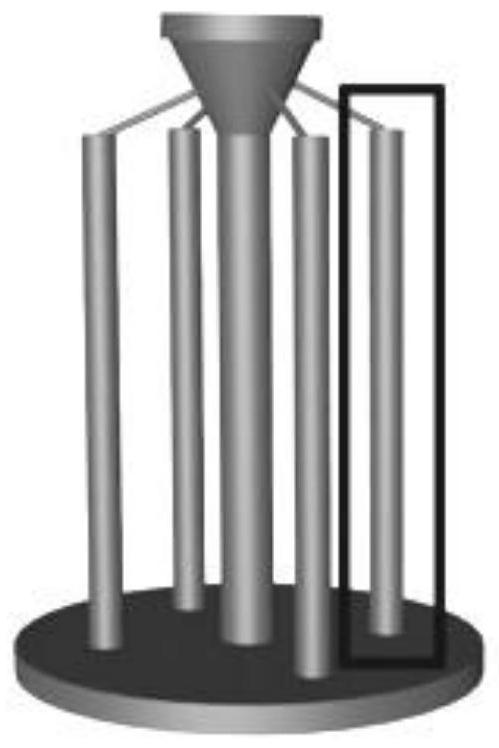
[0076] (1) Wax mold pretreatment: decontaminate the pressed wax mold and dry it for later use; the schematic diagram of the wax mold structure is shown in image 3 ,from image 3 It can be seen that the wax model includes five cylinders.
[0077] (2) Preparation of surface layer slurry: use silica sol and 320-mesh EC95 powder (EC95 powder is brown corundum sand made of 95% alumina and 5% silica fused and sintered) to prepare a slurry with a viscosity of 3.2mPa.s The surface layer slurry is ready for use;
[0078] (3) Preparation of surface layer: the surface layer slurry prepared in step (2) is used to coat and sand the surface layer slurry on the outer surface of the pressed wax mold, and then it is placed in the room to dry naturally for 12 hours to obtain the first composite structure. ; The sand in the sand is 70 mesh EC95 powder;
[0079] (4) Configure the transition layer slurry: use silica sol and 320 mesh EC95 powder to prepare a slurry with a viscosity of 3.1 mPa.s, which is used as the transition layer slurry for use;
[0080] (5) Preparation of transition layer: on the outer surface of the first composite structure obtained in step (3), the transition layer slurry prepared in step (4) is used to coat and hang, and after sanding, it is placed in a room for natural drying for 12 hours, A second composite structure is obtained; the sand in the sanding is 50 mesh EC95 powder;
[0081] (6) Configure the back layer slurry: use silica sol and 320 mesh EC95 powder to prepare a slurry with a viscosity of 3.0, which is used as the back layer slurry for use;
[0082] (7) Preparation of the first back layer: on the outer surface of the second composite structure obtained in step (5), the back layer slurry configured in step (6) is used to coat and hang, and after sanding, it is placed in a room for natural drying for 12h, The first back layer is prepared to obtain the third composite structure; the sand in the sand sprinkler is 20 mesh EC95 powder;
[0083](8) wrapping fiber cloth: coating epoxy resin on the outer surface of the third composite structure obtained in step (7), and then spirally winding the outer surface of the fourth composite structure coated with epoxy resin, from top to bottom Next, wrap a layer of carbon fiber tape (width of 10cm, thickness of 0.111mm, and the total length of the wax mold stick can be wrapped as a whole), and placed in the room to dry naturally for 12h to obtain the fourth composite structure; photo, see Figure 5. from Figure 5 It can be seen that the carbon fibers are tightly wrapped around the fourth composite structure.
[0084] (9) Preparation of the second back layer: on the outer surface of the fourth composite structure obtained in step (8), the operation of step (7) is repeated once to prepare a second back layer to obtain a fifth composite structure.
[0085] (10) Configure the sealing slurry: use silica sol and 320 mesh EC95 powder to prepare a slurry with a viscosity of 4.0 mPa.s, which is used as a sealing slurry for standby;
[0086] (11) Sealing slurry treatment: The sixth composite structure obtained in step (9) is coated and hung with the sealing slurry prepared in step (10), and then placed in the room for natural drying for 12 hours after sanding to obtain a finished coating and hanging solution. ceramic shell;
[0087] (12) Dewaxing: the coated ceramic shell obtained in step (11) is put into a dewaxing kettle, and dewaxing is carried out to obtain a ceramic shell precursor, and the dewaxing temperature is 170 ° C, and is completed within 5 minutes;
[0088] (13) Roasting: the ceramic shell precursor obtained in step (12) is roasted in a vacuum roasting furnace to obtain a ceramic shell; the roasting temperature is 1000° C., and the roasting time is 2 hours.
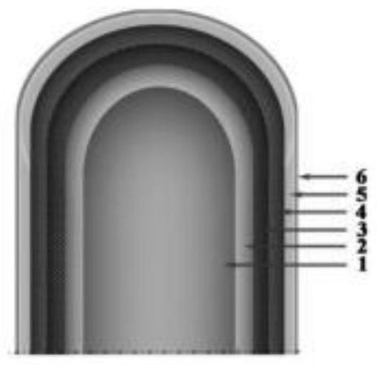
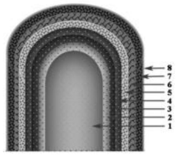
[0089] A schematic cross-sectional view of the ceramic shell prepared in Example 1 of the present invention, see figure 1; the three-dimensional schematic diagram of the columnar structure of the ceramic shell prepared in Example 1 of the present invention, see Figure 4;from figure 1 and Figure 4 It can be seen that the ceramic shell prepared by the present invention has 6 layers; the photo of the ceramic shell prepared in Example 1 of the present invention, see Image 6; The embodiment of the present invention 1 obtains the four columnar body sections of the ceramic shell, refer to Figure 7 ,from Figure 7 It can be seen that the ceramic shell prepared by the present invention is thinner and contains carbon fibers in the middle; the top view photo of the ceramic shell prepared in Example 1 of the present invention, see Figure 8 ,from Figure 8 It can be seen that the four cylindrical bodies on the outer side of the mold shell are sequentially numbered 1 to 4; for the photos of the thickness test of the four cylindrical bodies of the ceramic mold shell prepared in Example 1 of the present invention, see Figure 9 , It can be seen from 9 that the thicknesses of the four shapes numbered 1 to 4 are 6.02mm, 6.96mm, 5.59mm and 5.40mm in turn, with an average thickness of 5.99mm.
[0090] Preparation of single-crystal superalloy blades: in the directional solidification equipment, the ceramic shell obtained in step (13) is used as the shell for superalloy casting, directional solidification, and cooling to obtain single-crystal superalloy blades.

PUM

PropertyMeasurementUnit
Granularity60.0 ~ 80.0mesh
Granularity30.0 ~ 60.0mesh
Granularity16.0 ~ 30.0mesh
tensileMPa
Particle sizePa
strength10

Description & Claims & Application Information

We can also present the details of the Description, Claims and Application information to help users get a comprehensive understanding of the technical details of the patent, such as background art, summary of invention, brief description of drawings, description of embodiments, and other original content. On the other hand, users can also determine the specific scope of protection of the technology through the list of claims; as well as understand the changes in the life cycle of the technology with the presentation of the patent timeline. Login to view more.

Similar technology patents

Classification and recommendation of technical efficacy words

  • High strength
  • Reduce the number of layers

Pressure-control well-drilling method and device based two gradients

ActiveCN101070755ASimplify well structureReduce the number of layersAutomatic control for drillingOffshore drillingFluid control
Owner:CHINA NAT OFFSHORE OIL CORP +1

Method and apparatus for realizing double-gradient well drilling

ActiveCN1932234ASimplify well structureReduce the number of layersUnderwater drillingFlushingWater pipeIt equipment
Owner:CHINA NAT OFFSHORE OIL CORP +1

Method for preparing graphene by pulling jelly

ActiveCN105502367AReduce the number of layersThe number of layers is evenly distributedMaterial nanotechnologyGraphenePhysicsChemistry
Owner:CHENDU NEW KELI CHEM SCI CO LTD

Preparation method of graphene

Owner:OCEANS KING LIGHTING SCI&TECH CO LTD +1
Why Eureka
Try Eureka