High-gain converter for photovoltaic direct-current module and control method of high-gain converter

A DC module and control method technology, applied in the field of converters, can solve the problems of high voltage stress of power devices, large number of power devices, and low reliability, so as to reduce capacitance and volume, reduce the number of power tubes, and improve reliability. sexual effect

Inactive Publication Date: 2022-06-03
NANTONG UNIVERSITY
View PDF1 Cites 0 Cited by
  • Summary
  • Abstract
  • Description
  • Claims
  • Application Information

AI Technical Summary

Problems solved by technology

Boost converters based on coupled inductors can obtain higher voltage gain by changing the winding ratio of coupled inductors, but the conversion efficiency is usually low due to the difficulty of effectively recovering leakage inductance energy
The multi-module extended switched inductor Boost converter changes the connection mode of the inductor by controlling the switch off and on, so as to obtain a higher voltage gain; however, there are a large number of power devices, and the voltage stress of the power devices is high. Low efficiency and other disadvantages
Moreover, the input current has a large pulsation, and a large-capacity filter capacitor needs to be connected in parallel on the input side, resulting in a large system size, cost, and low reliability.

Method used


Image

  • High-gain converter for photovoltaic direct-current module and control method of high-gain converter
  • High-gain converter for photovoltaic direct-current module and control method of high-gain converter
  • High-gain converter for photovoltaic direct-current module and control method of high-gain converter

Examples


Embodiment Construction

[0035] The technical solutions in the embodiments of the present application will be clearly and completely described below with reference to the drawings in the embodiments of the present application. Obviously, the described embodiments are only a part of the embodiments of the present application, rather than all the embodiments. Based on the embodiments in the present application, all other embodiments obtained by persons of ordinary skill in the art without creative efforts shall fall within the protection scope of the present invention.

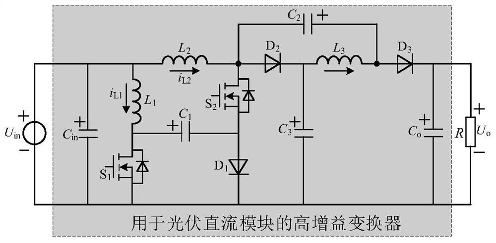
[0036] The invention provides a high-gain converter for a photovoltaic DC module, the circuit structure is as follows figure 1 shown. The high gain converter includes an input filter capacitor C in , the first capacitor C 1 , the second capacitor C 2 , the third capacitor C 3 , output filter capacitor C o , the first inductance L 1 , the second inductance L 2 , the third inductor L 3 , the first switch tube S 1 , the second swi...


PUM

PropertyMeasurementUnit
capacitanceaaaaaaaaaa

Abstract

The invention belongs to the technical field of converters, and discloses a high-gain converter for a photovoltaic direct-current module and a control method of the high-gain converter. The positive electrode of an input filter capacitor of the converter is connected with one end of a first inductor and one end of a second inductor; the other end of the first inductor is connected with the drain electrode of the first switch tube and the positive electrode of the first capacitor; the other end of the second inductor is connected with the drain electrode of the second switch tube, the anode of the second diode and the cathode of the second capacitor; the source electrode of the second switch tube is connected with the cathode of the first capacitor and the anode of the first diode; the cathode of the second diode is connected with one end of the third inductor and the anode of the third capacitor; the other end of the third inductor is connected with the anode of the third diode and the anode of the second capacitor; and the cathode of the third diode D3 is connected with the anode of the output filter capacitor. The high-gain converter has the advantages of being high in boosting capacity, few in power tubes, small in input current ripple and the like.

Description

technical field [0001] The invention belongs to the technical field of converters, and in particular relates to a high-gain converter for photovoltaic DC modules and a control method thereof. Background technique [0002] Inverter is a key component of photovoltaic grid-connected power generation system, which is mainly divided into centralized, string, AC module (ie micro-inverter), parallel DC module (ie power optimizer) and other types. The first two types of inverters have high conversion efficiency, but require a large number of photovoltaic modules to be used in series and parallel. Under the condition of partial shading, it will be difficult to find the global maximum power point due to the multi-peak phenomenon of the P-V characteristic curve of the photovoltaic array. Unleash the power generation potential of each component. Micro-inverters can realize the maximum power point tracking control at the component level, and have the advantages of flexible installation,...

Claims


Application Information

Patent Timeline
Patent Type & Authority Applications(China)
IPC IPC(8): H02M3/158H02M1/088H02M1/14
CPCH02M3/158H02M1/088H02M1/14Y02E10/56
Inventor 秦岭许兴张雷王亚芳杨毓钱娇孙诗雨刘宇涵周磊段冰莹钱天泓
Owner NANTONG UNIVERSITY
Why Eureka
Try Eureka