Method for capturing carbon dioxide from flue gas

A carbon dioxide and flue gas technology, applied in chemical instruments and methods, separation methods, alkali metal oxides/hydroxides, etc., can solve the problem of low adsorption capacity, achieve high removal depth, easy regeneration, and high selectivity sexual effect

Active Publication Date: 2022-06-28
ZHEJIANG NORMAL UNIVERSITY
View PDF6 Cites 0 Cited by
  • Summary
  • Abstract
  • Description
  • Claims
  • Application Information

AI Technical Summary

Problems solved by technology

However, due to the constraints of the nature of these traditional adsorption materials, the adsorption capacity is generally low.

Method used


Image

  • Method for capturing carbon dioxide from flue gas
  • Method for capturing carbon dioxide from flue gas
  • Method for capturing carbon dioxide from flue gas

Examples


Embodiment 1

[0044] In a 50 mL round bottom flask, 241.6 mg (1 mmol) of Cu(NO 3 ) 2 ·3H 2 O and 197.9 mg (1 mmol) of (NH 4 ) 2 TiF 6 Dissolve in 14mL of water. In another 50 mL round bottom flask, 331.05 mg (1.3 mmol) of tris(4-pyridyl)amine (L1) was dissolved in 30 mL methanol. The methanol solution was added dropwise to the aqueous solution and stirred at 30°C for 48 hours to obtain a purple solid precipitate, which was filtered and washed with methanol. The above-mentioned solid was immersed in anhydrous methanol, and the anhydrous methanol was replaced every six hours for more than 3 times in total to remove the water molecules in the pores of the material, and the column cage metal organic framework material (CuTiF) was obtained. 6 ) 3 (L1) 4 .

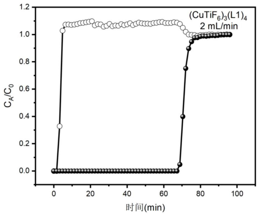
[0045] (CuTiF 6 ) 3 (L1) 4 Grind into fine powder of uniform size, put it into an adsorption column with an inner diameter of 0.5 cm and a length of 5 cm, activate it at 120 °C for 10 hours, and at room temperature of 25 °C, pass ...

Embodiment 2

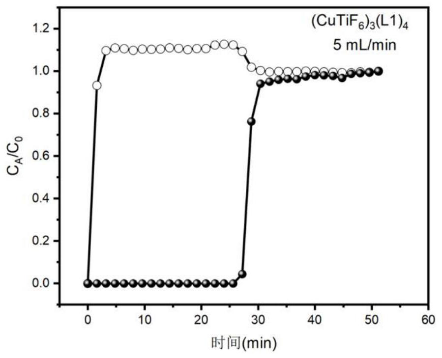
[0047] The adsorption column (inner diameter 0.5cm, length 5cm) of embodiment 1, at room temperature 25 ℃, the nitrogen / carbon dioxide gas mixture is passed into the adsorption column at 5mL / min, the nitrogen with extremely low carbon dioxide content is obtained in the first 26min, and the adsorption is stopped. At 50°C, the carbon dioxide gas was desorbed under vacuum. N 2 / CO 2 (v:v=85:15) mixture in (CuTiF 6 ) 3 (L1) 4 The penetration curve on the figure 2 shown.

Embodiment 3

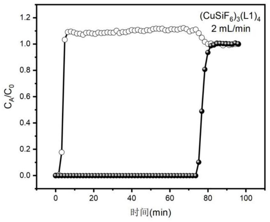
[0049] In a 50 mL round bottom flask, 277.7 mg (1 mmol) of CuSiF 6 Dissolve in 14mL of water. In another 50 mL round bottom flask, 331.05 mg (1.3 mmol) of tris(4-pyridyl)amine (L1) was dissolved in 30 mL methanol. The methanol solution was added dropwise to the aqueous solution, and stirred at 30° C. for 48 hours to obtain a purple-red solid precipitate, which was filtered and washed with methanol. The above-mentioned solid was immersed in anhydrous methanol, and the anhydrous methanol was replaced every six hours for more than 3 times in total to remove the water molecules in the material holes to obtain a column cage-type metal organic framework material (CuSiF). 6 ) 3 (L1) 4 .

[0050] Grind the adsorbent into fine powder of uniform size, put it into an adsorption column with an inner diameter of 0.5 cm and a length of 5 cm, activate it at 120°C for 10 hours, and mix nitrogen / carbon dioxide (v:v=85:15) at room temperature of 25°C The gas was passed into the adsorption ...


PUM

PropertyMeasurementUnit
adsorption capacityaaaaaaaaaa

Abstract

The invention discloses a method for capturing carbon dioxide from flue gas, which comprises the following step of: selectively adsorbing carbon dioxide in the flue gas by using an anion-containing hydrothermal stable column cage type metal-organic framework material as an adsorbent. The structure of the anion-containing hydrothermal stable column cage type metal-organic framework material is that hexa-coordinated metal ions M and a tridentate nitrogen-containing ligand L are coordinated to form a cage type structure, and then the cage type structure is connected through inorganic anions A to form a cross-linked column cage type structure. According to the method provided by the invention, carbon dioxide can be captured from the flue gas in a high-capacity and high-selectivity manner, the removal depth is high, the adsorbent is easy to regenerate, and the hydrothermal stability is good.

Description

technical field [0001] The invention relates to the technical field of chemical separation, in particular to a method for capturing carbon dioxide from flue gas. Background technique [0002] In recent years, with the rapid economic development, the widespread use of fossil fuels emits a large amount of carbon dioxide which will cause the greenhouse effect. As people pay more and more attention to the global climate environment, the international voice for carbon emission control is getting louder and louder. For controlling carbon emissions, the treatment of industrial flue gas is particularly important, which contains a large amount of CO 2 , the composition of conventional gas, oil and coal as fuel flue gas is as follows: N 2 82%~89%, CO 2 8%~15%, O 2 3% to 5% and a small amount of SO 2 and nearly saturated water vapor. [0003] To address this conundrum, over the past few decades, researchers have prepared a variety of new materials (activated carbon, molecular ...

Claims


Application Information

Patent Timeline
Patent Type & Authority Applications(China)
IPC IPC(8): B01D53/04B01J20/22B01J20/28B01J20/30
CPCB01D53/04B01D53/0407B01J20/226B01J20/28014B01D2257/504B01D2257/102B01D2258/0283B01J2220/58Y02C20/40
Inventor 张袁斌姜芸佳汪玲瑶吴依莲袁燕斌
Owner ZHEJIANG NORMAL UNIVERSITY
Why Eureka
Try Eureka