Yellow phosphorus tail gas deep purification system and deep purification method

A technology for deep purification of yellow phosphorus tail gas, applied in chemical instruments and methods, separation methods, air quality improvement, etc., can solve problems such as poor utilization of CO resources, rapid boiler corrosion, high cost of tail gas resource utilization, and achieve CO resource utilization High utilization rate, low P2O5 content, and low cost of tail gas resource utilization

Pending Publication Date: 2022-07-08
CECEP INDAL ENERGY CONSERVATION
View PDF3 Cites 0 Cited by
  • Summary
  • Abstract
  • Description
  • Claims
  • Application Information

AI Technical Summary

Problems solved by technology

[0008] The purpose of the present invention is to provide a deep purification system for yellow phosphorus tail gas, which solves the problems of poor CO resource utilization, fast boiler corrosion, and P 2 o 5 A series of problems such as the high content of waste gas and the high cost of resource utilization of tail gas

Method used


Image

  • Yellow phosphorus tail gas deep purification system and deep purification method
  • Yellow phosphorus tail gas deep purification system and deep purification method
  • Yellow phosphorus tail gas deep purification system and deep purification method

Examples


Embodiment 1

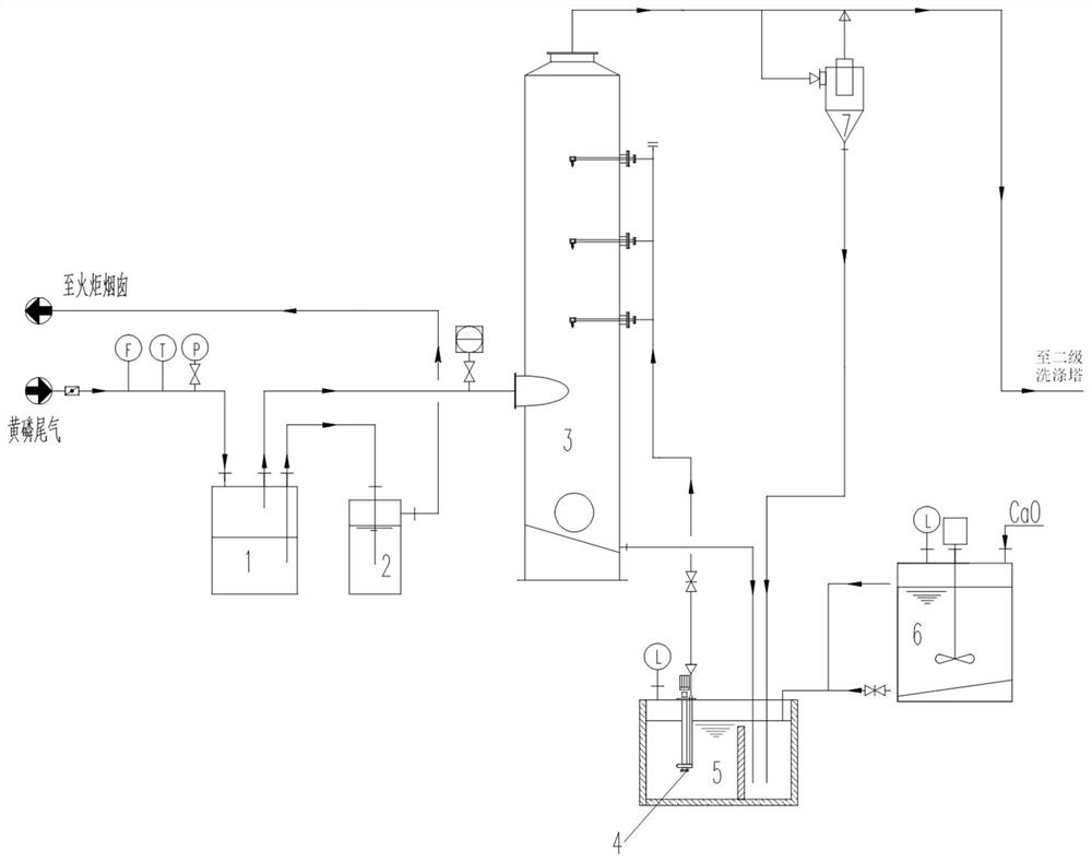
[0066] of the present invention Figure 1-Figure 4 It is a diagram of each part of the system of the present invention, and combining all the parts together is a schematic diagram of the overall structure of the system of the present invention.

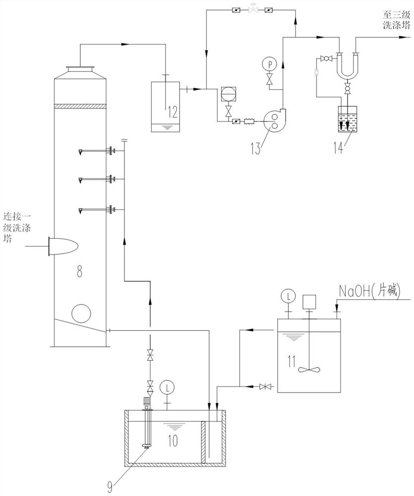
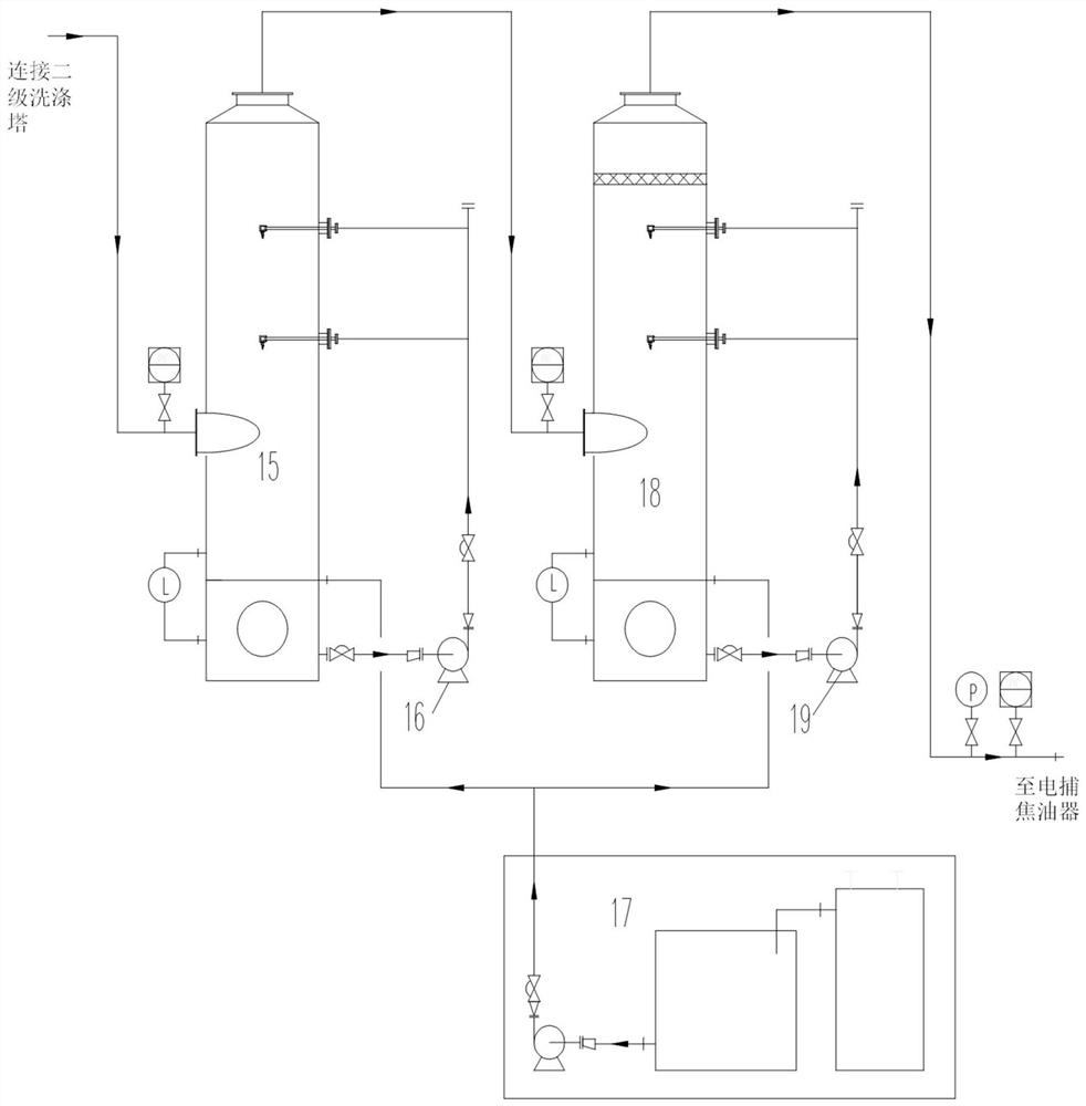
[0067] like Figure 1-4 As shown in the figure, a deep purification system for yellow phosphorus tail gas, the system includes a first-stage washing tower 3, a cyclone demister 7, a second-stage washing tower 8, a third-stage washing tower 15, a fourth-stage washing tower 18, and an electric tar catcher. 20 and activated carbon adsorption tower 21;

[0068] The air inlet of the primary washing tower 3 is connected to the yellow phosphorus tail gas, the air outlet of the primary washing tower 3 is connected to the air inlet of the cyclone demister 7, and the air outlet of the cyclone demister 7 is connected to the air inlet of the secondary washing tower 8 The liquid outlet of the first-level washing tower 3 is connected to the liqui...

Embodiment 2

[0082] Adopt the yellow phosphorus tail gas deep purification method of the yellow phosphorus tail gas deep purification system of embodiment 1, described method comprises the steps:

[0083] 1) The yellow phosphorus tail gas enters the primary washing tower through the primary tail gas water seal. When the system fails, the passage from the primary tail gas water seal to the primary washing tower is closed, and the yellow phosphorus tail gas is released to the flare chimney through the secondary tail gas water seal;

[0084] 2) The yellow phosphorus tail gas is sprayed and washed by the first-level washing tower, the second-level washing tower, the third-level washing tower and the fourth-level washing tower, and enters the electric tar catcher. NaOH solution is used for washing, and the third-stage washing tower and the fourth-stage washing tower are washed with oxidant solution for wet oxidative dephosphorization;

[0085] 3) The tar in the yellow phosphorus tail gas is rem...


PUM


Abstract

The invention belongs to the field of yellow phosphorus tail gas resource utilization, and particularly relates to a deep purification system and a deep purification method for yellow phosphorus tail gas. The deep purification system comprises a first-stage washing tower, a cyclone demister, a second-stage washing tower, a third-stage washing tower, a fourth-stage washing tower, an electrical tar precipitator and an activated carbon adsorption tower, and the first-stage washing tower, the cyclone demister, the second-stage washing tower, the third-stage washing tower, the fourth-stage washing tower, the electrical tar precipitator and the activated carbon adsorption tower are connected in series. According to the invention, a series of problems of poor CO resource utilization rate, fast boiler corrosion, high P2O5 content in the purified tail gas, high tail gas resource utilization cost and the like in the existing yellow phosphorus tail gas purification treatment and power generation process are solved.

Description

technical field [0001] The invention belongs to the field of resource utilization of yellow phosphorus tail gas, and particularly relates to a deep purification system and a deep purification method for yellow phosphorus tail gas used for power generation. Background technique [0002] In the technical field involved in the present invention, the current state of the art is that the production of yellow phosphorus is mainly produced by electrothermal method, using phosphate rock, silica, coke (or white coal) as raw materials, and reacting under high temperature conditions to generate elemental phosphorus and rich in phosphorus CO exhaust. In addition to carbon monoxide (volume fraction) of about 85-90% in the exhaust gas, there are also some gases such as hydrogen fluoride, phosphorus, phosphine, hydrogen sulfide, etc., which will form acid rain after combustion and seriously pollute the environment. At present, the application and treatment of yellow phosphorus tail gas ma...

Claims


Application Information

Patent Timeline
IPC IPC(8): B01D53/78B03C1/30B01D53/75
CPCB01D53/78B01D50/00B01D53/75Y02E20/12
Inventor 杨业建毕秀荣杨立新陆涛任育杰武汉河何成国王哲阮征刘双林于志军苏广通张安强
Owner CECEP INDAL ENERGY CONSERVATION
Why Eureka
Try Eureka