Waste lithium ion battery recycling device and method with flue gas purification function
A lithium-ion battery and flue gas purification technology, which is applied in battery recycling, mixers with rotating stirring devices, separation methods, etc., can solve the problems of insufficient contact between waste lithium-ion batteries and warm air, long drying time, etc., and achieve Improve stirring efficiency, expand stirring range, and improve drying efficiency
- Summary
- Abstract
- Description
- Claims
- Application Information
AI Technical Summary
Problems solved by technology
Method used
Image
Examples
Embodiment 1
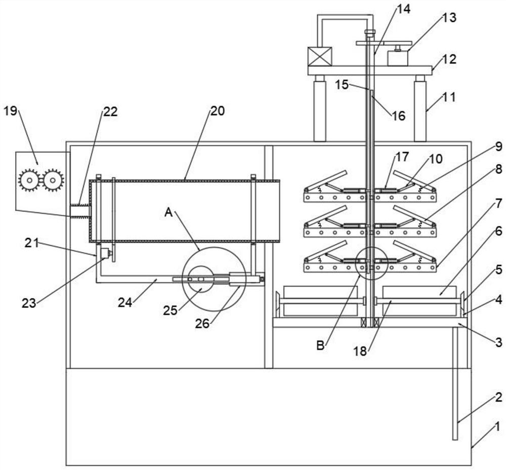
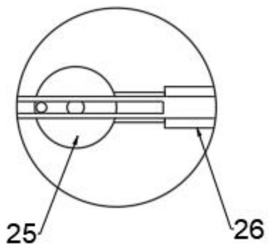
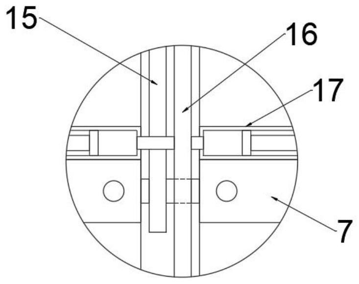
[0045] see Figure 1-3 , In the embodiment of the present invention, the waste lithium-ion battery recycling and processing device with the function of flue gas purification includes a box body 1 and a drying unit, and a box door is installed on the box body 1. In this embodiment, the box door is preferably The box body 1 is connected with the box body 1 through hinges and buckles. The box body 1 is provided with a drying cavity. The drying unit includes a hot air blower and a stirring assembly. The stirring assembly includes a stirring shaft 14, a stirring rod 7, and a driving stirring shaft 14 to rotate. The first drive mechanism 13 and the movable plate 3 are located in the oven, the stirring shaft 14 is vertically arranged in the drying cavity, and the top of the stirring shaft 14 moves through the top of the box body 1 and the mounting plate 12 and extends to the top of the mounting plate 12. The shaft 14 is rotatably connected with the mounting plate 12. An electric push...
Embodiment 2
[0048] see Figure 4-5 On the basis of Embodiment 1, this embodiment further, the open end of the filter cartridge 20 is fixed with a third motor through a plurality of support rods, and the output shaft of the third motor is fixed with an L-shaped shaft 27, so The L-shaped shaft 27 is hinged with a plurality of support plates 28 at intervals, and a second spring is connected between the support plate 28 and the L-shaped shaft 27, and the L-shaped shaft 27 is driven to rotate eccentrically by the third motor, and the L-shaped shaft 27 drives the support plate. 28 rotates, which can block and further control the cutting speed.
Embodiment 3
[0050] see Image 6 , this embodiment is based on Embodiment 2. In the specific implementation, a mobile unit is installed in the installation cavity at the bottom of the box body 1, and the mobile unit includes an installation rod 31, a roller and a power mechanism. The installation cavity Mounting rods 31 are hinged on the two side walls respectively. The bottom end of the mounting rod 31 is rotatably installed with rollers. Multiple mounting rods can be installed, or multiple rollers can be installed on one mounting rod at intervals, so as to ensure the stability during movement. The power mechanism is used to drive the installation rod 31 to rotate;
[0051] Further, the power mechanism includes a fourth motor, a spur gear 29 and a second connecting rod 30. There are two spur gears 29 in total and are meshed side by side. The fourth motor is drivingly connected to one spur gear 29 and two spur gears 29. The end faces are eccentrically hinged with second connecting rods 30...
PUM
 Abstract
Description
Claims
Application Information
 - R&D
- Intellectual Property
- Life Sciences
- Materials
- Tech Scout
- Unparalleled Data Quality
- Higher Quality Content
- 60% Fewer Hallucinations
Browse by: Latest US Patents, China's latest patents, Technical Efficacy Thesaurus, Application Domain, Technology Topic, Popular Technical Reports.
© 2025 PatSnap. All rights reserved.Legal|Privacy policy|Modern Slavery Act Transparency Statement|Sitemap|About US| Contact US: help@patsnap.com


