Photocatalyst for CO2 reduction-biomass oxidation coupling reaction and preparation method thereof
A photocatalyst, oxidative coupling technology, applied in catalyst activation/preparation, physical/chemical process catalyst, carbon monoxide, etc., can solve the problems of limited coupling reaction efficiency, photoresponse and poor photogenerated electron-hole separation ability, and achieve excellent performance, the effect of realizing separation ability
- Summary
- Abstract
- Description
- Claims
- Application Information
AI Technical Summary
Problems solved by technology
Method used
Image
Examples
Embodiment 1
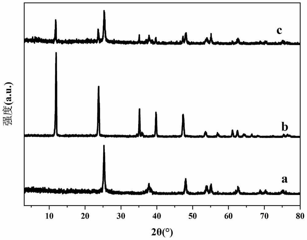
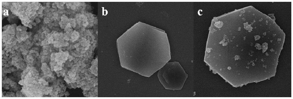
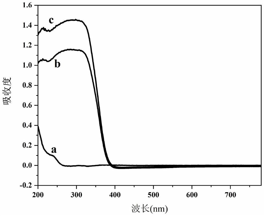
[0036] A: Weigh 0.004mol of Mg(NO 3 ) 2 ·6H 2 O and 0.002 mol of Al (NO 3 ) 3 ·9H 2 O powder, dissolved in a beaker with 30 mL of deionized water.
[0037] B: Weigh 0.03mol of urea and 0.6000g of TiO 2 powder, into a beaker containing 30 mL of deionized water.
[0038] C: Add the above two solutions to another beaker at the same time, through vigorous stirring and ultrasonic dispersion, until the TiO 2 The powder is uniformly dispersed in the solution to obtain MgAl-LDH / TiO 2 The suspension was transferred to the reactor, aged at 120°C for 24h, centrifuged and washed to neutralize the filtrate; dried at 50°C for 12h, taken out and ground into powder to obtain MgAl-LDH / TiO 2 Photocatalysts, of which TiO 2 The mass ratio to MgAl-LDH is 1.
[0039] The above-prepared photocatalysts were used to drive CO by light 2 Reduction-5-HMF oxidation coupling reaction experiment:
[0040] Dissolve 30 mg of catalyst powder in 60 mL of 0.02 g / L 5-HMF solution, put it into a top-il...
Embodiment 2
[0042] A: Weigh 0.006mol of Ni(NO 3 ) 2 ·6H 2 O and 0.002mol Fe(NO 3 ) 3 ·9H 2 O powder, dissolved in a beaker containing 30 mL of deionized water.
[0043] B: Weigh 0.02mol of urea and 0.3000g of Cu 2 O solid, feeding into a beaker filled with 30 mL of deionized water.
[0044] C: Add solution A and suspension B to the beaker at the same time, and stir vigorously and ultrasonically disperse until Cu 2 O powder is uniformly dispersed in the solution to obtain NiFe-LDH / Cu 2 O suspension; transferred to the reactor, aged at 100°C for 12h, washed and centrifuged until neutral; dried at 60°C for 12h, taken out, and ground into powder to obtain NiFe-LDH / Cu 2 O photocatalyst, where Cu 2 The mass ratio of O to NiFe-LDH is 0.6.
Embodiment 3
[0046] A: Weigh 0.004mol of Zn(NO 3 ) 2 ·6H 2 O and 0.002 mol of Cr (NO 3 ) 3 ·9H 2 O powder, dissolved in a beaker containing 30 mL of deionized water.
[0047] B: Weigh 0.04mol of urea and 1.2000g of CeO 2 The solid was charged into a beaker containing 30 mL of deionized water.
[0048] C: Add solution A and suspension B to the beaker simultaneously, and stir vigorously and ultrasonically disperse until CeO 2 The powder is uniformly dispersed in the solution to obtain ZnCr-LDH / CeO 2 the suspension; transferred to the reactor, aged at 150 °C for 36 h, washed and centrifuged until neutral; dried at 60 °C for 12 h, taken out, and ground into powder to obtain ZnCr-LDH / CeO 2 Photocatalysts in which CeO 2 The mass ratio to ZnCr-LDH is 3.
PUM
 Abstract
Description
Claims
Application Information
 - R&D
- Intellectual Property
- Life Sciences
- Materials
- Tech Scout
- Unparalleled Data Quality
- Higher Quality Content
- 60% Fewer Hallucinations
Browse by: Latest US Patents, China's latest patents, Technical Efficacy Thesaurus, Application Domain, Technology Topic, Popular Technical Reports.
© 2025 PatSnap. All rights reserved.Legal|Privacy policy|Modern Slavery Act Transparency Statement|Sitemap|About US| Contact US: help@patsnap.com


