Micro-droplet capture microfluidic structure, chip with micro-droplet capture microfluidic structure and capture/release method

A microfluidic chip, microdroplet technology, applied in chemical instruments and methods, laboratory utensils, laboratory containers, etc., can solve the problem of unfavorable droplet sorting and recovery, difficult droplet release, chip geometry Complexity and other problems, to achieve the effect of micro-droplet capture, reduced difficulty, and high-throughput micro-droplet capture

Pending Publication Date: 2022-07-29
HANGZHOU TINKER BIOTECHNOLOGY CO LTD
View PDF0 Cites 0 Cited by
  • Summary
  • Abstract
  • Description
  • Claims
  • Application Information

AI Technical Summary

Problems solved by technology

At present, the commonly used droplet capture method is mainly the geometrically induced droplet capture method, that is, the drople

Method used


Image

  • Micro-droplet capture microfluidic structure, chip with micro-droplet capture microfluidic structure and capture/release method
  • Micro-droplet capture microfluidic structure, chip with micro-droplet capture microfluidic structure and capture/release method
  • Micro-droplet capture microfluidic structure, chip with micro-droplet capture microfluidic structure and capture/release method

Examples


Example Embodiment

[0037] Example 1:

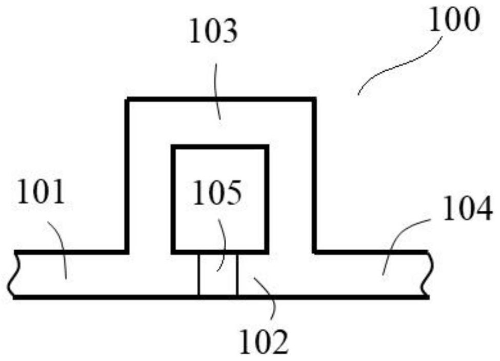
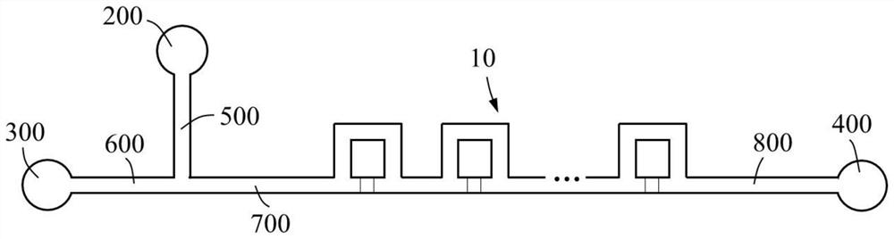
[0038] see attached figure 1 , the embodiment of the present invention discloses a micro-droplet capture microfluidic structure, including a micro-droplet capture unit 10, a droplet capture area 105 is set on the microchannel of the micro-droplet capture unit 10, and the droplet capture area 105 is set Media layer that captures microdroplets.

[0039] The microchannel includes a microchannel unit 100. The microchannel unit 100 includes a first flow channel 102 and a second flow channel 103. Both ends of the first flow channel 102 are an inlet channel 101 and an outlet channel 104. The second flow channel 103 is connected in parallel with the first flow channel 102. Between the inlet channel 101 and the outlet channel 104 ; the medium layer is arranged in the first flow channel 102 between the inlet channel 101 and the outlet channel 104 .

Example Embodiment

[0040] Example 2:

[0041] On the basis of Example 1, the microdroplets are water-in-oil microdroplets, the medium layer has a hydrophilic surface, and the microchannels have a hydrophobic material layer or are made of a hydrophobic material.

[0042] In order to further optimize the above technical solution, the material of the hydrophilic surface is glass, and the layer of hydrophobic material or the hydrophobic material is PDMS.

Example Embodiment

[0043] Example 3:

[0044] On the basis of Example 1, the microdroplets are oil-in-water microdroplets, the medium layer has a hydrophobic surface, and the microchannels have a hydrophilic material layer or are made of a hydrophilic material.

[0045] In order to further optimize the above technical solution, the material of the hydrophobic surface is PDMS, and the hydrophilic material layer or the hydrophilic material is glass.


PUM


Abstract

The invention discloses a micro-droplet capturing micro-fluidic structure, a chip with the micro-droplet capturing micro-fluidic structure and a capturing/releasing method, the micro-droplet capturing micro-fluidic structure comprises a micro-droplet capturing unit, a micro-channel of the micro-droplet capturing unit is provided with a droplet capturing area, and the droplet capturing area is provided with a medium layer for capturing micro-droplets; the micro-droplet capturing micro-fluidic chip comprises a micro-droplet generating unit and the micro-droplet capturing unit, wherein a micro-channel outlet of the micro-droplet generating unit is communicated with a micro-channel inlet of the micro-droplet capturing unit; according to the micro-droplet capturing/releasing method, the micro-droplet capturing unit or the micro-droplet capturing micro-fluidic chip is adopted, and the micro-droplets captured by the dielectric layer are controlled to be released from the droplet capturing area by controlling the micro-channel flow velocity of the micro-droplet capturing unit. According to the invention, the geometric structure of the micro-fluidic chip is simplified, and the difficulty of liquid drop sorting and recovery is reduced.

Description

technical field [0001] The invention relates to the technical field of droplet microfluidics, in particular to a microdroplet capture microfluidic structure based on a hydrophilic and hydrophobic patterned surface, a chip having the same, and a capture / release method. Background technique [0002] Microfluidic technology is a technology for manipulating fluids at the micro-nano scale. It can integrate basic operation units such as sample processing, biochemical reactions, analysis and detection involved in biology, chemistry and other fields on a chip with a size of several square centimeters. It can not only greatly reduce the consumption of reagent samples, etc., but also significantly improve the efficiency and throughput of the reaction. As an important branch of microfluidic technology, droplet microfluidic technology is mainly used to produce trace amounts (10 -5 ~10 -9 L) Liquid cells, ie microdroplets, to perform experimental manipulations. The microdroplets are i...

Claims


Application Information

Patent Timeline
IPC IPC(8): B01L3/00
CPCB01L3/5027
Inventor 宋乐叶嘉明
Owner HANGZHOU TINKER BIOTECHNOLOGY CO LTD
Why Eureka
Try Eureka