Polishing device for photovoltaic sheet machining

A chip processing and photovoltaic technology, applied to machine tools, metal processing equipment, grinding machines, etc., which are suitable for grinding workpiece planes, can solve the problems of inconvenient removal of alignment structures, lack of processing functions, unfavorable and efficient automatic grinding, etc., to achieve The effect of automatic reciprocating grinding

Pending Publication Date: 2022-07-29
江苏林洋光伏运维有限公司
9 Cites 0 Cited by

AI-Extracted Technical Summary

Problems solved by technology

[0003] However, at present, the processing of photovoltaic sheets is mainly realized by knives or edging machines, which lack the processing function that can quickly and automat...

Method used

In the process that hexagonal shaft 602 rotates, driving transmission cover 701 rotates, and transmission cover 701 drives transmission shaft A704 rotation by bevel gear, and transmission shaft A704 drives transmission shaft B705 rotation by bevel gear, and transmission shaft B705 drives frosting by bevel gear The wheel 706 rotates, and the convex strip 703 fits the beveled edge of the buckle frame 303 and presses th...

Abstract

The invention provides a polishing device for photovoltaic sheet machining, and relates to the technical field of polycrystalline silicon machining, the polishing device comprises a base, the top of the base is of a flat plate structure; the L-shaped frame is fixedly arranged on one side of the top of the base, and a telescopic air rod is fixedly arranged at the bottom of the front end of the L-shaped frame; a middle shaft is fixedly arranged in the middle of the bottom of the square table, the bottom of the middle shaft is rotationally arranged at the top of the base in cooperation with a conical roller bearing, and the middle shaft is aligned with the circle center of the telescopic air rod; a hexagonal shaft and a grinding wheel provide a machining function capable of rapidly and automatically grinding and providing a flanging effect, a motor is started to drive the hexagonal shaft to rotate, a moving seat can be pushed to approach a silicon wafer, the grinding wheel is driven to rotate, grinding can be guaranteed, a rack drives a limiting ring and a square table to rotate and change edges in the reset process, automation is achieved, and the machining efficiency is improved. The problem that an existing edge grinding device lacks the machining functions of rapidly and automatically grinding and providing the flanging effect is solved.

Application Domain

Grinding carriagesGrinding work supports +3

Technology Topic

PhysicsSilicon chip +6

Image

  • Polishing device for photovoltaic sheet machining
  • Polishing device for photovoltaic sheet machining
  • Polishing device for photovoltaic sheet machining

Examples

  • Experimental program(1)

Example Embodiment

[0035] Example: please refer to Figure 1 to Figure 10 :
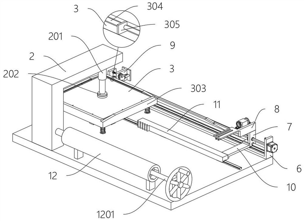
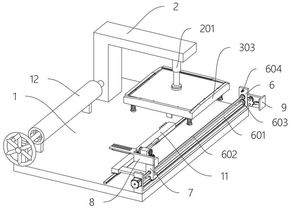
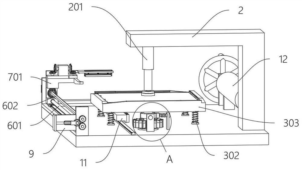
[0036] The present invention provides a polishing device for photovoltaic sheet processing, comprising: a base 1, the top of which is a flat plate structure; an L-shaped frame 2, which is fixedly arranged on one side of the top of the base 1, and the L-shaped frame A telescopic gas rod 201 is fixedly arranged at the bottom of the front end of 2, and the L-shaped frame 2 also includes: a rotating rubber block 202, the bottom end of the telescopic gas rod 201 is rotatably provided with a rotating rubber block 202 with a bearing; An intermediate shaft 301 is fixedly arranged in the middle of the bottom, and the bottom of the intermediate shaft 301 is rotatably arranged on the top of the base 1 with the tapered roller bearing, and the intermediate shaft 301 is aligned with the center of the telescopic gas rod 201; the outer side of the intermediate shaft 301 is fixedly provided with an inner ratchet gear 5; a connecting rod 10 is fixedly arranged on the rear side of the moving base 7, a rack 11 is fixedly arranged on the rear side of the connecting rod 10, and the rack 11 is slidably arranged on the top of the base 1 with the guide rail, and the number of teeth of the rack 11 is the inner ratchet gear 5 1/4; limit ring 4, the limit ring 4 is fixedly arranged on the middle outer side of the intermediate shaft 301; U-shaped frame 6, the U-shaped frame 6 is fixedly arranged on the front side of the top of the base 1; the movable seat 7, the movable seat 7 is slidably arranged on the inner side of the U-shaped frame 6 through the guide rail; the pressing piece 8 is fixedly arranged on the top rear side of the movable seat 7; A pressing roller 802 is arranged to rotate on the inner side, and a spring is arranged between the lower side of the sliding frame 801 and the pressing piece 8; a T-shaped piece 9, the T-shaped piece 9 is fixedly arranged on the front side of the U-shaped frame 6 close to one end of the L-shaped frame 2; The air piston 12 and the air control piston 12 are fixedly arranged on the top rear side of the base 1 .
[0037] Furthermore, according to embodiments of the present invention, reference is made to Figure 10, the base 1 includes: a limit pile 101, the top of the base 1 is fixedly provided with three sets of limit piles 101, the limit pile 101 is located on the outer side of the intermediate shaft 301; the inclined pin 102, the outer side of the intermediate shaft 301 is fixed with a spring rod A103 , the spring rod A103 is sleeved with a spring and passes through the limit pile 101, and the self-locking function is provided by the spring rod A103.
[0038] Furthermore, according to embodiments of the present invention, reference is made to figure 1 and Figure 5 , the square table 3 also includes: spring rods B302, four groups of spring rods B302 are fixedly arranged at the top corners of the square table 3; a buckle edge frame 303, the buckle edge frame 303 is fitted and buckled under the side of the square table 3, The top of the corner side of the buckle frame 303 is an inclined surface; the spring rod B302 passes through the buckle frame 303 to sleeve a spring and is fixedly provided with a stopper; an inner guide rod 304 is fixedly provided with an inner guide rod 304 on the inner side of the edge of the square table 3 The inner guide rod 304 is slidably provided with two groups of moving cards 305. The moving cards 305 are aligned with the edge of the square table 3. The alignment of the moving cards 305 with the side of the photovoltaic sheet where no paint is attached can provide an alignment and fixation function.
[0039] Furthermore, according to embodiments of the present invention, reference is made to Figure 10 , the limit ring 4 includes: V groove 401, the outer side of the limit ring 4 is provided with four groups of V grooves 401, and the three groups of oblique pins 102 are matched and arranged in the V groove 401 to complete the alignment and self-locking, and limit the limit ring 4 Rotate 90° each time.
[0040] Furthermore, according to embodiments of the present invention, reference is made to figure 2 , the U-shaped frame 6 includes: a main screw 601, the inner side of the U-shaped frame 6 is rotatably provided with a main screw 601; a hexagonal shaft 602, a hexagonal shaft 602 is rotated above the inner side of the U-shaped frame 6; The transmission gear 603, the main screw 601 and the end of the hexagonal shaft 602 close to the T-shaped member 9 are rotatably provided with two sets of transmission gears 603, and the two sets of transmission gears 603 are not in contact; Proximity switches 604 are fixedly arranged on each of them; the hexagonal shaft 602 provides a continuous rotation function, and a motor is arranged on one side of the U-shaped frame 6 to be connected with the hexagonal shaft 602 for transmission.
[0041] Furthermore, according to embodiments of the present invention, reference is made to Image 6 , the movable seat 7 includes: a transmission sleeve 701, a transmission sleeve 701 is rotatably provided on the lower side of the movable seat 7, and the transmission sleeve 701 is slidably connected with the hexagonal shaft 602; the upper clamping seat 702, a top side of the movable seat 7 is fixedly provided with The upper card seat 702, the rear side of the upper card seat 702 is fixedly provided with a convex strip 703, and the bottom of the outer end of the convex strip 703 is an inclined surface structure; the transmission shaft A704, the front side of the upper clamping base 702 is rotatably provided with a transmission shaft A704, and a transmission sleeve 701 A bevel gear transmission connection is set with the transmission shaft A704; the transmission shaft B705, the top of the upper holder 702 is rotated and provided with a transmission shaft B705, and the transmission shaft B705 is connected with the transmission shaft A704 by a bevel gear transmission; A grinding wheel 706 is provided in the side rotation, the transmission shaft B705 is connected with the grinding wheel 706 by a bevel gear, and the grinding wheel 706 can contact the edge of the silicon wafer for grinding.
[0042] Furthermore, according to embodiments of the present invention, reference is made to Figure 8 , T-shaped member 9 includes: sliding shaft frame 901, two sides of T-shaped member 9 are slidably provided with sliding shaft frame 901 through guide rails; electric cylinder 902, two sets of electric cylinders are fixedly arranged on both sides of T-shaped member 9 902, the telescopic end of the electric cylinder 902 is fixedly connected with the electric cylinder 902; the connecting gear 903, the front sides of the two sets of sliding axle frames 901 are respectively provided with a set of connecting gears 903 and two sets of connecting gears 903, and two sets of connecting gears 903 on the same side Meshing, one set of connecting gears 903 provides co-rotation, and two sets of connecting gears 903 provide reversal.
[0043] Furthermore, according to embodiments of the present invention, reference is made to Figure 9 , the gas control piston 12 includes: an inner screw 1201, the inner screw 1201 is arranged in the middle of the gas control piston 12; 1202 is threadedly connected with the inner screw 1201; connecting pipe 1203, one end of the gas control piston 12 is provided with a connecting pipe 1203, which is connected to the telescopic gas rod 201 through the interior of the L-shaped frame 2.
[0044] The specific use method and function of this embodiment: In the present invention, when using, place the silicon wafer on the top of the square table 3, and move the moving card 305 to attach the edge of the silicon wafer to the position where the paint is not attached to provide a fixing effect. Fix the silicon wafer, then rotate the inner screw 1201 to push the octagonal piston 1202 through threaded transmission, input the air in the air control piston 12 into the telescopic air rod 201, press the rotating rubber block 202, and use the rotating rubber block 202 to press and fix the silicon to complete the preset.
[0045] The starter motor drives the hexagonal shaft 602 to rotate, the hexagonal shaft 602 uses the transmission gear 603 to drive the connecting gear 903 and another group of transmission gears 603 to rotate, and the other group of transmission gears 603 drives the main screw 601 to rotate, which is propelled and moved through the thread drive The seat 7 is close to the side of the silicon wafer.
[0046] During the rotation of the hexagonal shaft 602, the transmission sleeve 701 is driven to rotate, the transmission sleeve 701 drives the transmission shaft A704 to rotate through the bevel gear, the transmission shaft A704 drives the transmission shaft B705 to rotate through the bevel gear, and the transmission shaft B705 drives the grinding wheel 706 to rotate through the bevel gear. , the protruding strips 703 fit the oblique edge of the buckle frame 303 during the movement and press the buckle frame 303 to expose the side of the silicon wafer to ensure grinding. The stress avoids chipping of the silicon wafer, and the pressing roller 802 can automatically adapt to the thickness of the silicon wafer with the spring.
[0047] When the moving base 7 moves to the edge of the square table 3, the proximity switch 604 is triggered, the electric cylinder 902 is extended and another group of electric cylinders 902 is retracted, and the other side connecting gear 903 meshes with the transmission gear 603 and reverses the main screw 601, making the moving base 7 Reset; the rack 11 drives the limit ring 4 and the square table 3 to rotate 90° during the reset process, the oblique pin 102 cooperates with the spring rod A103 to realize self-locking and fixation, and the side change is completed, and the moving seat 7 contacts another group of proximity switches 604 The moving direction of the moving seat 7 can be switched again when the four sides are polished, and the motor will automatically stop after the four sides are polished.

PUM

no PUM

Description & Claims & Application Information

We can also present the details of the Description, Claims and Application information to help users get a comprehensive understanding of the technical details of the patent, such as background art, summary of invention, brief description of drawings, description of embodiments, and other original content. On the other hand, users can also determine the specific scope of protection of the technology through the list of claims; as well as understand the changes in the life cycle of the technology with the presentation of the patent timeline. Login to view more.
Why Eureka
Try Eureka