Bidirectional multi-beam traveling wave cascade amplifier based on cold cathode

A cold cathode, multi-cascade technology, applied in the cathode of the transit time type electron tube, the circuit components of the transit time type electron tube, etc. restrictions, etc.

Active Publication Date: 2022-07-29
UNIV OF ELECTRONICS SCI & TECH OF CHINA
View PDF12 Cites 0 Cited by
  • Summary
  • Abstract
  • Description
  • Claims
  • Application Information

AI Technical Summary

Problems solved by technology

[0004] Traditional microwave tubes (such as traveling wave tubes, klystrons, return wave tubes and magnetrons, etc.) have made great achievements in the development of millimeter-wave bands, but continuing to advance in this direction will encounter fundamental limitations
The size of the high-frequency system of traditional microwave tubes must be compatible with the working wavelength. With the continuous increase of the operating frequency of the device, the size of the high-frequency system is getting smaller and smaller. On the one hand, it will bring difficulties in manufacturing and assembly. On the other hand, It also makes the space and time for the interaction between the electron beam and the high-frequency field smaller and smaller, making the speed and density modulation of the electron beam insufficient, and the interaction efficiency and output power of the device are severely limited; it is this reason that has become a traditional Serious obstacles to the development of microwave tubes to millimeter wave, submillimeter wave, and terahertz frequency bands

Method used


Image

  • Bidirectional multi-beam traveling wave cascade amplifier based on cold cathode
  • Bidirectional multi-beam traveling wave cascade amplifier based on cold cathode
  • Bidirectional multi-beam traveling wave cascade amplifier based on cold cathode

Examples


Embodiment Construction

[0018] The present invention will be further described in detail below with reference to the accompanying drawings and implementations, so as to make the purpose, technical solutions and technical effects of the present invention clearer and more complete.

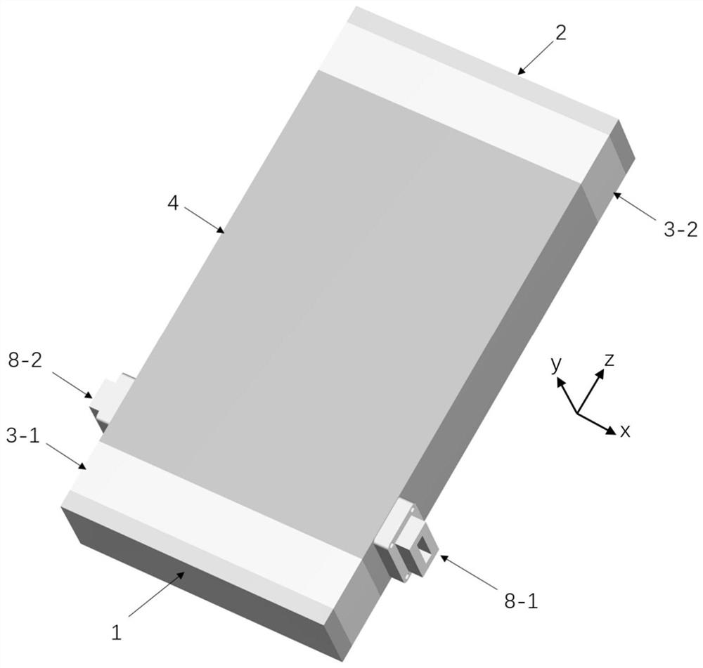
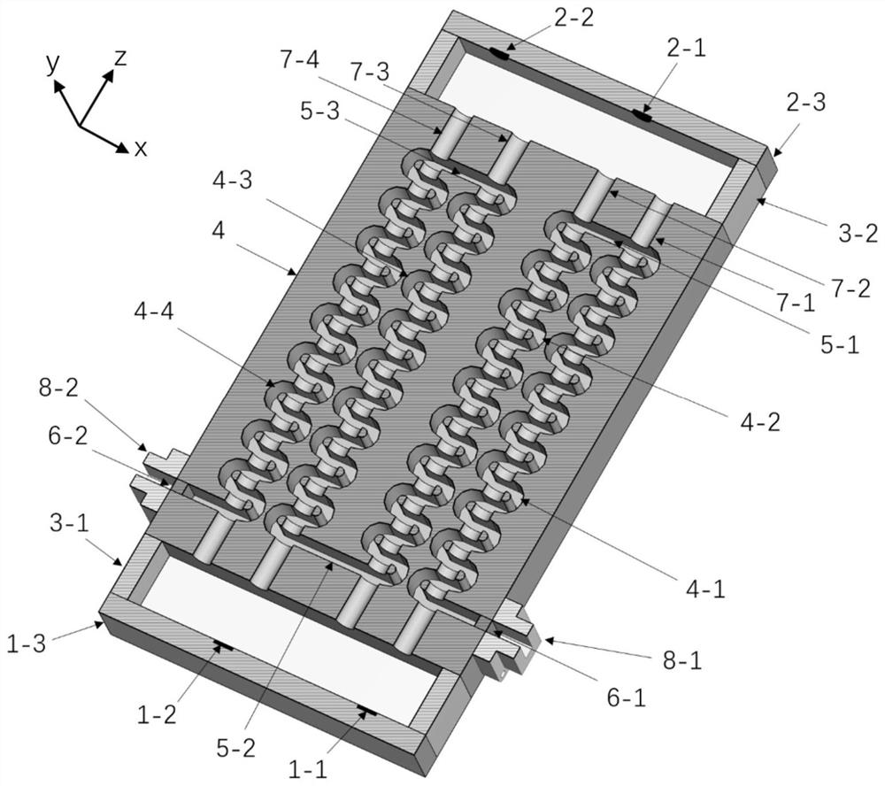
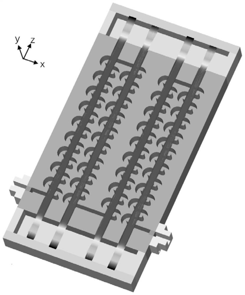
[0019]This embodiment provides a wide-band and high-efficiency traveling wave cascade amplifier based on bidirectional multi-electron injection of cold cathode, taking the structure of multi-emitting end-face multi-electron injection cold cathode injection interaction amplifier for W-band as an example , whose structure is as figure 1 , figure 2 shown in the figure, wherein the X direction is the long side dimension direction, the Y axis direction is the high side dimension direction, and the Z axis direction is the broad side dimension direction; specifically including: specifically including: a multi-cascade folded waveguide slow-wave circuit 4, which is insulated through the front end The front-end cold cathode flat e...


PUM


Abstract

The invention belongs to the field of microwave, millimeter wave and terahertz frequency range vacuum electronic devices, and provides a bidirectional multi-beam traveling wave cascade amplifier based on a cold cathode, which adopts a multi-electron-beam traveling wave cascade array structure formed by a plurality of pairs of traveling wave slow wave structures and cold cathode plate electron guns at the front end and the rear end. Each pair of traveling-wave slow-wave structures is composed of an input-stage slow-wave circuit and an output-stage slow-wave circuit which are arranged side by side, the traveling-wave slow-wave structures are communicated with each other through rectangular coupling grooves, and the input-stage slow-wave circuit and the output-stage slow-wave circuit are communicated with each other through rectangular coupling grooves; due to the fact that the slow-wave circuit has the broadband characteristic and the electromagnetic energy signal can be transmitted and amplified along the traveling-wave slow-wave circuit and the coupling groove, it is guaranteed that the whole system has the broadband characteristic and has the gain superposition effect by cascading the multiple pairs of traveling-wave slow-wave structures. Moreover, the whole circuit has a good energy recovery mechanism, and finally, the broadband high-gain high-interaction-efficiency broadband high-gain high-interaction-efficiency broadband high-gain high-interaction-efficiency broadband high-gain high-interaction-efficiency broadband high-gain high-interaction

Description

technical field [0001] The invention belongs to the field of vacuum electronic devices in microwave, millimeter wave and terahertz frequency bands, and specifically provides a cold cathode-based bidirectional multi-electron injection, traveling wave cascade amplifier with wide frequency band and high efficiency. Background technique [0002] As an important part of modern military applications and many fields of the national economy, vacuum electronic devices have a wide range of applications in communications, radar, electronic countermeasures, satellite communications, radio astronomy, radio stations, and medical diagnosis and treatment. However, since the end of the 20th century, with the rapid development of the semiconductor industry and integrated circuit technology, vacuum electronic devices have gradually lost their dominant position in a considerable electronic information field, and are suffering the impact of the development of solid-state electronic devices. Howe...

Claims


Application Information

Patent Timeline
Patent Type & Authority Applications(China)
IPC IPC(8): H01J23/24H01J23/04
CPCH01J23/24H01J23/04
Inventor 袁学松俎一帆崔仲韬鄢扬王彬李海龙殷勇蒙林
Owner UNIV OF ELECTRONICS SCI & TECH OF CHINA
Why Eureka
Try Eureka