
High-speed sweep-frequency optical fiber light source

A technology of fiber optic light source and frequency-sweeping light source, which is applied in lasers, laser components, and material analysis through optical means, and can solve problems such as inability to present high-quality OCT imaging

Pending Publication Date: 2022-07-29
HEFEI UNIV OF TECH
View PDF0 Cites 0 Cited by
  • Summary
  • Abstract
  • Description
  • Claims
  • Application Information

AI Technical Summary

Problems solved by technology

None of the above frequency-sweeping light sources can present high-quality OCT imaging at a fast speed

Method used


Image

  • High-speed sweep-frequency optical fiber light source
  • High-speed sweep-frequency optical fiber light source
  • High-speed sweep-frequency optical fiber light source

Examples


Embodiment Construction

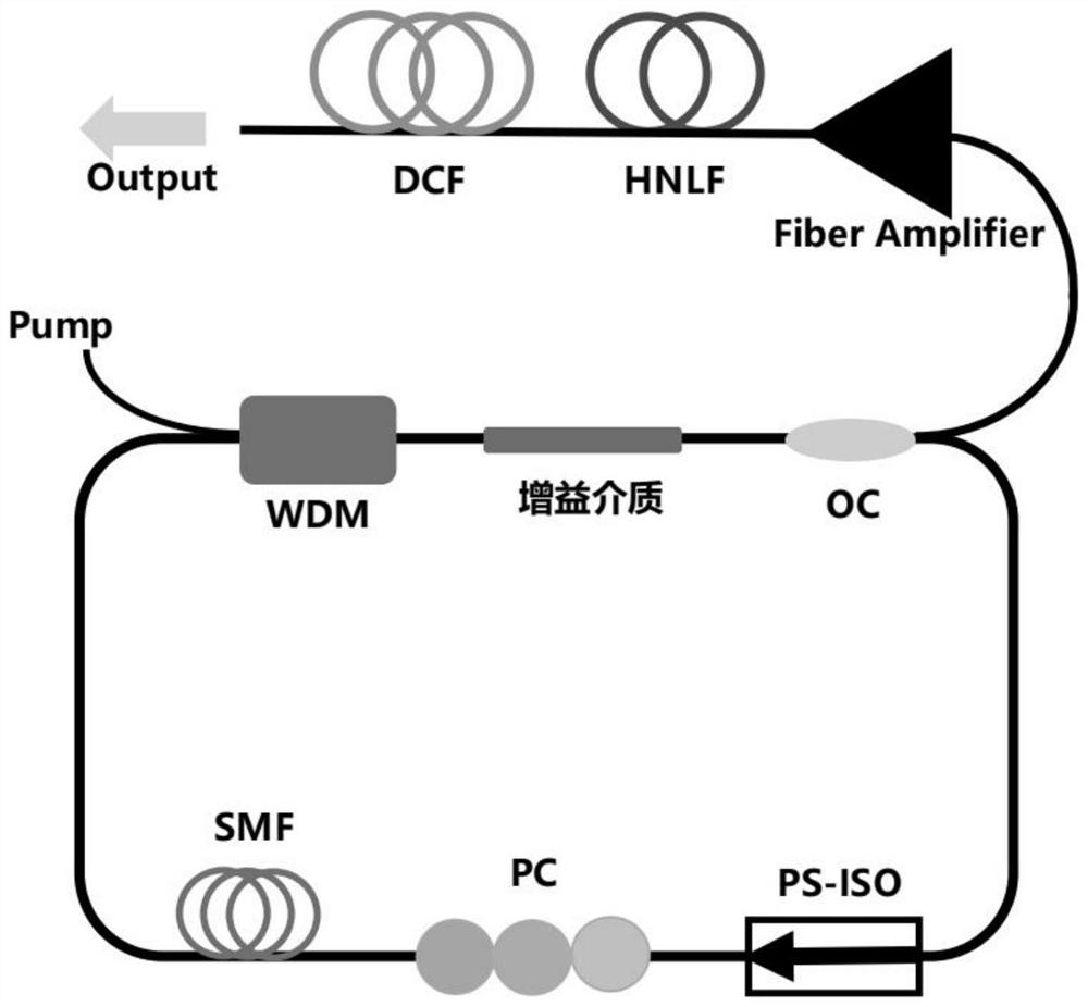
[0028] The technical solutions in the embodiments of the present invention will be clearly and completely described below with reference to the accompanying drawings in the embodiments of the present invention.

[0029] like Figure 1-2 As shown, the device structure consists of a pulse seed source, a fiber amplifier, a high nonlinear fiber, and a dispersion compensation fiber; the pulse seed source consists of a wavelength division multiplexer, a gain medium, a polarization-dependent isolator, a polarization controller, a single Mode fiber and output coupler. In the example, a monochromatic laser light source with a working wavelength of 980 nm is used as the pump light source, and then a wavelength division multiplexer (WDM) is used to gain and flow into a section of low erbium-doped fiber with a length of 10 m; the device adopts polarization dependent isolation. The PS-ISO suppresses the backward feedback to ensure the unidirectional operation of the ring cavity laser; and...


PUM


Abstract

The invention discloses a high-speed sweep-frequency optical fiber light source which specifically comprises a mode-locked pulse light source, an optical fiber amplifier, a high-nonlinearity optical fiber and a dispersion compensation optical fiber, a passive mode-locked pulse light source outputs a high-repetition-frequency wide-spectrum mode-locked pulse, dispersion transmission of the high-repetition-frequency wide-spectrum mode-locked pulse follows a parabolic differential equation similar to one-dimensional paraxial diffraction and is analogous to Fraunhofer diffraction, and the high-repetition-frequency wide-spectrum mode-locked pulse is obtained. Laser pulse energy and peak power of the pulse are improved through an optical fiber amplifier outside the cavity, then a super-continuum spectrum light source is obtained through broadening of a high-nonlinearity optical fiber, and finally after the pulse is stretched through a large dispersive medium provided by a dispersive optical fiber, a pulse frequency domain spectrum is mapped to a time domain waveform, so that a high-speed frequency sweeping light source in a time domain is realized.

Description

technical field [0001] The invention belongs to the technical field of optical fiber lasers, and in particular relates to a high-speed frequency sweep optical fiber light source. Background technique [0002] Optical coherence tomography (OCT) technology is a new method for high-resolution cross-sectional imaging of transparent and translucent sample tissues, introduced in 1991, and has been widely used in many fields in recent years, especially in the biomedical field. As an important part of the OCT system, the swept-frequency light source has broad development space and application prospects, so it has considerable feasibility and practical significance for the research and development of high-speed swept-frequency light sources. [0003] The main swept-frequency light sources used in OCT systems are: short-cavity lasers, swept-frequency vertical-cavity surface-emitting lasers, and Fourier frequency-domain mode-locked lasers. The laser wavelength of the short-cavity lase...

Claims


Application Information

Patent Timeline
IPC IPC(8): H01S3/067H01S3/098H01S3/00G01N21/45G01N21/01
CPCH01S3/06754H01S3/1112H01S3/005H01S3/0057G01N21/45G01N21/01G01N2021/0112G01N2201/061
Inventor 周勇常艺暄高伟清马晓辉方文坛陈小林
Owner HEFEI UNIV OF TECH
Learn More