Environment-friendly metal scrap collecting equipment for cutting equipment

A metal chip and cutting equipment technology, applied in metal processing equipment, metal processing machinery parts, separation methods, etc., can solve the problems of easy falling into the sieve hole, high humidity of metal chips, and easy rusting of iron chips, etc. problem, to achieve the effect of improving recycling rate, improving space utilization rate and improving recycling effect

Active Publication Date: 2022-08-09
SUZHOU NEW DISTRICT ENVIRONMENTAL PROTECTION SERVICE CENT CO LTD
View PDF21 Cites 2 Cited by
  • Summary
  • Abstract
  • Description
  • Claims
  • Application Information

AI Technical Summary

Problems solved by technology

[0004] But the above-mentioned invention has the following disadvantages: when the above-mentioned patent is used, some smaller debris is still easy to fall into the sieve hole and cause blockage; and the surface of the debris separated by the conical single-blade fan of the above-mentioned patent will inevitably remain Part of the cutting fluid, resulting in high humidity of the separated metal chips, it takes a long time to dry naturally, some iron chips are easy to rust, which is not conducive to the subsequent recovery of metal chips

Method used


Image

  • Environment-friendly metal scrap collecting equipment for cutting equipment
  • Environment-friendly metal scrap collecting equipment for cutting equipment
  • Environment-friendly metal scrap collecting equipment for cutting equipment

Examples


Embodiment Construction

[0034]The present invention will be described in detail below, and the technical solutions in the embodiments of the present invention will be clearly and completely described. Obviously, the described embodiments are only a part of the embodiments of the present invention, rather than all the embodiments. Based on the embodiments of the present invention, all other embodiments obtained by those of ordinary skill in the art without creative efforts shall fall within the protection scope of the present invention.

[0035] The present invention provides an environmentally friendly metal chip collection device for cutting equipment by improving, and the technical scheme of the present invention is:

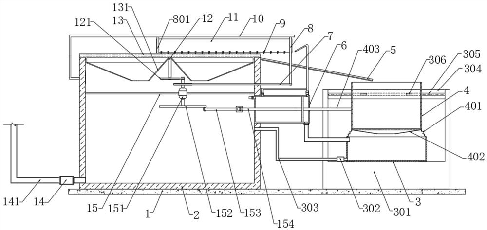
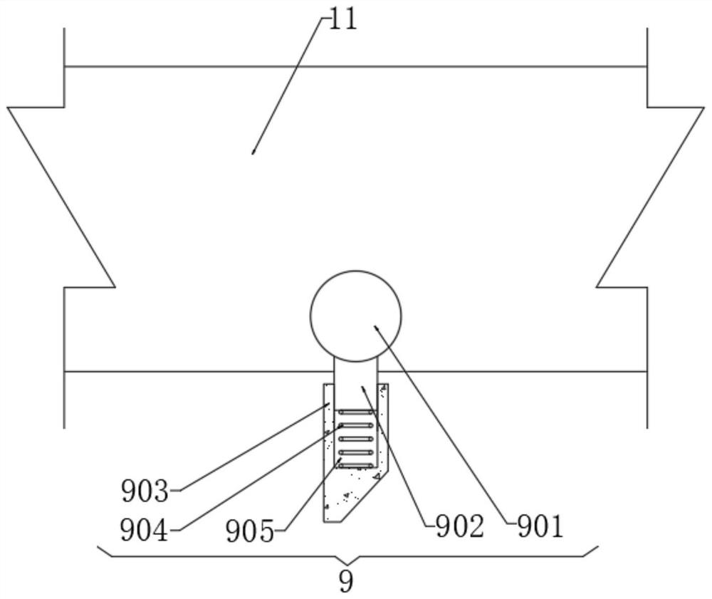
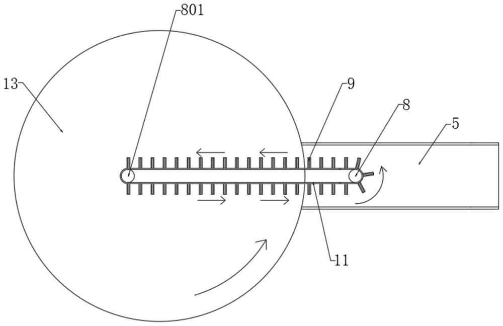
[0036] like Figure 1 to Figure 8 As shown in the figure, the embodiment of the present invention provides an environmentally friendly metal debris collection device for cutting equipment, including a mounting substrate 1, and a liquid collecting tank box 2 and a suction filter botto...


PUM


Abstract

The invention discloses environment-friendly metal scrap collecting equipment for cutting equipment, and relates to the technical field of metal processing, the environment-friendly metal scrap collecting equipment comprises a mounting base plate, a liquid collecting tank and a suction filtration bottom box are arranged on the two sides of the outer wall of the top of the mounting base plate respectively, and the liquid collecting tank is fixed to the mounting base plate; the piston plate can move under the action of a follow-up driving assembly, when the piston plate moves towards the first exhaust pipe, air at one end of the piston plate can be pressed into the air outlet mother pipe through the first one-way air valve, and meanwhile, the second exhaust pipe extracts air from the interior of the liquid collecting tank; when the piston plate moves towards the second exhaust pipe, air at the other end is pressed into the air outlet branch pipe and the air outlet main pipe through the second one-way air valve, meanwhile, the first exhaust pipe extracts air from the suction filtration bottom box, in conclusion, the negative pressure assembly can enable the interiors of the liquid collecting tank box and the suction filtration bottom box to be in a negative pressure state, and therefore the suction filtration effect is achieved; and the recovery effect on the cutting fluid is further improved.

Description

technical field [0001] The invention relates to the technical field of metal processing, in particular to an environment-friendly metal chip collection device for cutting equipment. Background technique [0002] The metal cutting process is a process of interaction between the workpiece and the tool. The tool removes excess metal from the workpiece to be processed, so that the workpiece can obtain geometric accuracy, dimensional accuracy and surface quality that meet the design and process requirements. During the cutting process, metal debris will be mixed in the cutting fluid, and the metal debris cannot be reasonably recovered, which wastes resources. [0003] After retrieval, the publication number is CN112791445A patent document, which discloses an environmentally friendly metal scrap collection device applied to cutting equipment, including a guide device, a mounting seat, a sealing cover, a solid-liquid separation mechanism, a waste liquid collection device, and debri...

Claims


Application Information

Patent Timeline
Patent Type & Authority Applications(China)
IPC IPC(8): B01D33/17B01D33/46B01D33/76B01D36/02B23Q11/00B23Q11/10C10M175/00
CPCB01D33/17B01D33/466B01D36/02B01D33/76B23Q11/0042B23Q11/0067B23Q11/1069C10M175/00Y02P70/10
Inventor 吴鑫王艳秋张玲吴亮力李超
Owner SUZHOU NEW DISTRICT ENVIRONMENTAL PROTECTION SERVICE CENT CO LTD
Why Eureka
Try Eureka