Tailing pond overflow culvert anti-seepage method

An overflow culvert and anti-seepage technology, applied in the field of tailings pond flood discharge system governance, can solve problems such as easy deformation and cracking at the culvert wall or culvert pipe interface, and achieve the effect of improving bearing performance, improving effect and reducing cracking.

Pending Publication Date: 2022-08-09
河南安钢集团舞阳矿业有限责任公司
View PDF11 Cites 0 Cited by
  • Summary
  • Abstract
  • Description
  • Claims
  • Application Information

AI Technical Summary

Problems solved by technology

[0003] In view of this, the purpose of the present invention is to provide an anti-seepage method for the overflow culvert of the tailings pond, so as to solve the technical problem that the culvert wall or the joint of the culvert pipe is easily deformed and cracked in the prior art

Method used


Image

  • Tailing pond overflow culvert anti-seepage method
  • Tailing pond overflow culvert anti-seepage method

Examples


Embodiment 1

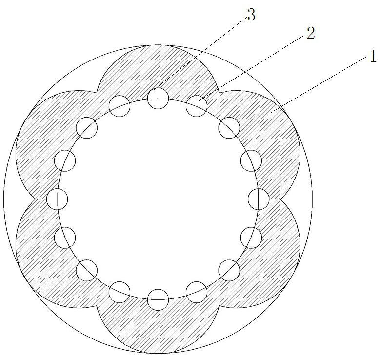
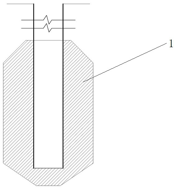
[0029] like figure 1 and figure 2 As shown, two rows of grouting holes are drilled in the vicinity of the leakage or injection point of the concrete pouring joints on the culvert wall, and each row includes 8 grouting holes, that is, 8 deep holes are drilled, and shallow holes 3 are also drilled. There are 8. The hole depth of deep hole 2 is 1.5m, the hole depth of shallow hole 3 is 0.5m, and the hole depth is reduced according to the actual situation in the lower part of the culvert.

[0030] The axis of the deep hole 2 is 75° to the culvert wall 1, the axis of the shallow hole 3 is 65° to the culvert wall 1, and the effective diffusion radius of each deep hole intersects with the effective radius of each shallow hole.

[0031] In a specific embodiment, deep holes are drilled first, and then shallow holes are drilled. Before drilling the shallow holes, it is necessary to ensure that grouting has been completed in each deep hole. In addition, before drilling the weak area ...

Embodiment 2

[0036] The difference between this embodiment 2 and the above-mentioned embodiment 1 is only:

[0037] The hole depth of the deep hole 2 is 2.5m, and the hole depth of the shallow hole 3 is 1.5m. The axis of the deep hole 2 is 70° to the culvert wall 1, and the axis of the shallow hole 3 is 70° to the culvert wall 1. The effective diffusion radius of each deep hole and the effective radius of each shallow hole still intersect.

[0038] The grouting pressure is controlled at 1.25MPa, and in the cement-water glass double-liquid slurry for deep hole injection, the water glass adopts an alkaline water glass with a modulus of 3.2 and a Baume degree of 45. In cement slurry, the water-cement ratio is in the range of 1:1. In the chemical slurry, the ratio of liquid A to liquid B is 10:5.

Embodiment 3

[0040] The difference between this embodiment 3 and the above-mentioned embodiment 1 is only:

[0041] The deep hole 2 has a hole depth of 1.5 m, and the shallow hole 3 has a hole depth of 1 m. The axis of the deep hole 2 is 65° to the culvert wall 1, and the axis of the shallow hole 3 is 75° to the culvert wall 1. The effective diffusion radius of each deep hole and the effective radius of each shallow hole still intersect.

[0042] The grouting pressure is controlled at 1.1MPa, and in the cement-water glass double-liquid slurry for deep hole injection, the water glass adopts an alkaline water glass with a modulus of 2.8 and a Baume degree of 40. In cement slurry, the water-cement ratio is in the range of 0.9:1. In the chemical slurry, the ratio of liquid A to liquid B is 10:3.

[0043] Of course, the anti-seepage method for the overflow culvert of the tailings pond of the present invention is not limited to the above three embodiments. For shallow holes, when grouting, us...


PUM


Abstract

The invention relates to an anti-leakage method for an overflow culvert of a tailing pond, which comprises the following steps of: drilling two rows of grouting holes near the front and back of a leakage or injection point of a concrete pouring joint of a culvert wall, and arranging each row of grouting holes in a plum blossom shape; a row of grouting holes located in front of a concrete pouring joint leakage or spraying point of the culvert wall are deep holes, and the depth of the deep holes ranges from 1 m to 2.5 m. A row of grouting holes located behind leakage or injection points of concrete pouring joints of the culvert wall are shallow holes, and the depth of the shallow holes is within the range of 0.5-1.5 m; an included angle of 65-75 degrees is formed between the axis of each grouting hole and the culvert wall, so that more permeable cracks in the tailing sand can be penetrated, and the effective diffusion radiuses of the grouting holes are intersected; cement and water glass double-liquid slurry is injected into each deep hole, and chemical slurry is injected into each shallow hole. According to the method, grouting is conducted behind the overflow culvert wall of the tailing pond, the culvert wall is effectively reinforced, silt is blocked behind the wall, culvert water seepage or silt spraying is well controlled, and normal use of the tailing pond is guaranteed.

Description

technical field [0001] The invention belongs to the technical field of tailings pond flood discharge system governance, and in particular relates to an anti-seepage method for overflow culverts of tailings ponds. Background technique [0002] With the increase of the accumulation thickness of the tailings in the tailings pond and the increase of the infiltration line in the tailings pond, the pressure on the overflow culvert wall is increasing. If muddy water or mortar is sprayed out, if the cracks are not blocked in time, the gaps will become more and more under the friction of the tailings mortar and finally cannot be blocked, and the sediment in the tailings pond will spew out, causing the dam collapse accident. In the prior art, in the event of leakage or injection, most of the holes are drilled within 1 meter near the leakage, insert a section of pipe with a valve (the valve is open) to relieve pressure, repair the culvert wall with anchoring agent, etc., and finally cl...

Claims


Application Information

Patent Timeline
Patent Type & Authority Applications(China)
IPC IPC(8): E02B3/16E02D15/00
CPCE02B3/16E02D15/00
Inventor 薛国平苗华邱合祥胡宾赵文兵范保卫苗晨迪顾志伟赵伟文启付李国建刘杰周军强陈明超
Owner 河南安钢集团舞阳矿业有限责任公司
Why Eureka
Try Eureka