Standing wave electronic straight line accelerator

A technology of linear accelerators and electrons, applied in the direction of linear accelerators, electrical components, accelerators, etc., can solve problems such as unfavorable electron beam focusing, image geometric blur, breakdown, etc., achieve remarkable focusing effects, shorten the overall length, and enhance focusing power Effect

Inactive Publication Date: 2005-09-21
SICHUAN DNDR DIGITAL RADIOGRAPHY TECH
View PDF0 Cites 2 Cited by
  • Summary
  • Abstract
  • Description
  • Claims
  • Application Information

AI Technical Summary

Problems solved by technology

(2) Since the X-ray source has a certain lateral size, the geometric blur ΔG of the image is caused
[0010] The nose cone is set in the acceleration chamber, which is not conducive to the focusing of the electron beam; due to the nose cone structure, the electric field strength in the acceleration chamber cannot be designed to be very large, otherwise breakdown will easily occur; the nose cone structure in the acceleration chamber makes machining difficult
[0011] This structure cannot significantly reduce the lateral size of the electron beam at the exit of the accelerator, and cannot more effectively meet the requirements of industrial CT imaging for X-ray sources

Method used


Image

  • Standing wave electronic straight line accelerator
  • Standing wave electronic straight line accelerator
  • Standing wave electronic straight line accelerator

Examples


Embodiment Construction

[0022] A standing wave electron linear accelerator of the invention will be further described below in conjunction with the accompanying drawings.

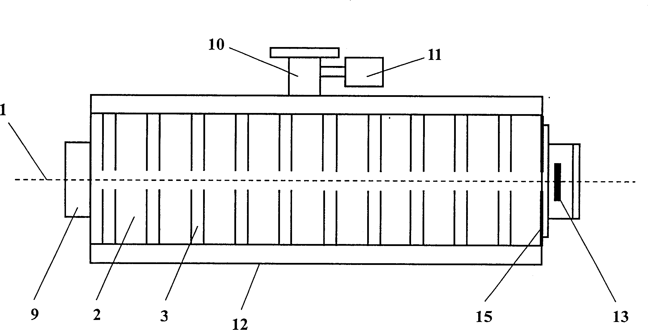
[0023] exist figure 1 It can be seen from the figure that the embodiment of the present invention includes an accelerating tube, an electron gun 9, a microwave coupler 10, a nose cone 5, a titanium pump 11, a constant temperature water jacket 12, and an accelerator power supply part and a tungsten target 13 matched therewith.

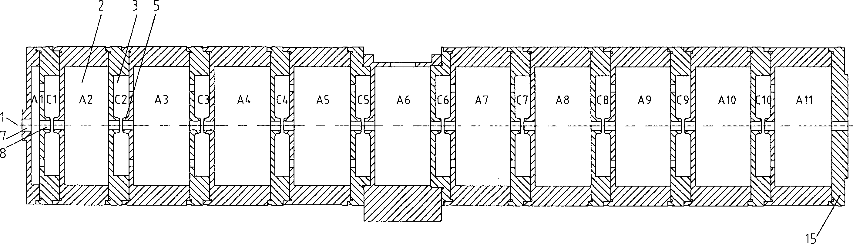
[0024] figure 2 It is an accelerating tube composed of multiple accelerating cavities 2 and coupling cavities 3, A1-A11 are accelerating cavities, C1-C10 are coupling cavities, and two nose cones 5 are arranged in each coupling cavity.

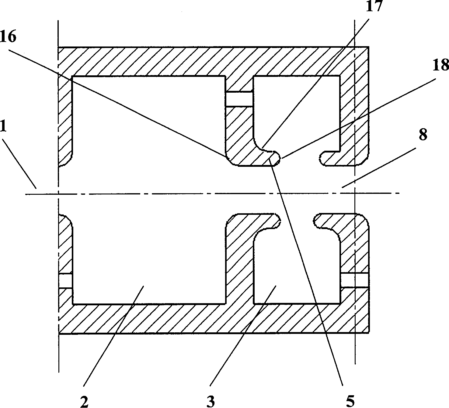
[0025] image 3 It is a schematic cross-sectional structure diagram of a coupling cavity 3 provided with a nose cone 5 and an adjacent accelerating cavity 2 .

[0026] A standing wave electron linear accelerator of the present invention comprises an accelerating tube, a...


PUM


Abstract

The invention provides a standing wave electron linear accelerator comprising accelerating chamber, coupling resonator, electron gun, microwave coupler, nose cone, titanium getter pump, thermostatic water jacket and tungsten target, wherein the nose cone is canceled from the accelerating chamber to be arranged in the couple resonator, two nose cones are arranged for each couple resonator on the front and rear end surfaces of the couple resonator. The accelerator by the present invention lowers the radial electric field intensity in the accelerating chamber, and maximize the output dosage.

Description

[0001] 1. Technical field: the invention belongs to the field of linear accelerators, in particular to a standing wave electron linear accelerator. 2. Background technology [0002] Computerized Tomography (CT for short) technology is an important field with rapid development in nuclear technology, and it is the product of the combination of nuclear physics, electronics, precision machinery and computer technology. Industrial CT (ICT) is the application of CT technology in industrial production inspection, and is entering the field of industrial production process control. It is a high-tech that is currently developing rapidly. High-energy industrial CT refers to the photon energy of the X-ray source in the system exceeding 1MeV. This high-energy X-ray can only be produced by an accelerator. The higher the energy of the X-ray, the stronger the penetrating ability, so the energy of the X-ray determines the size of the thickness of the workpiece to be inspected. [0003] A smal...

Claims


Application Information

Patent Timeline
Patent Type & Authority Patents(China)
IPC IPC(8): H05H9/04
Inventor 许州杨兴繁金晓黎明陈浩卢和平
Owner SICHUAN DNDR DIGITAL RADIOGRAPHY TECH
Why Eureka
Try Eureka